HOLLYLAND SOLIDCOM C1 Quick Guide V1.0.
Introduction Thank you for purchasing FULL-DUPLEX WIRELESS INTERCOM SYSTEM The SOLIDCOM C1 includes eight single-sided remote wireless headsets along with eight rechargeable batteries, a charger, a HUB base with wired headset, and accessories. It is a full-duplex wireless DECT intercom system engineered to provide clear audio and all-day wearing comfort in a true-wireless design with no beltpack required. The system operates in the 1.
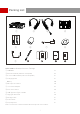
Packing List ① ⑤ ② ④ ③ ⑥ ⑧ ⑦ ⑨ SOLIDCOM C1 Headset Intercom Package ① HUB Base x1 ② Remote Headset (with blue nameplate) x8 ③ 3.
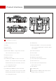
Product Interfaces ① ② ③ ④ ⑤⑥ ⑦ ⑧ ⑨ ⑩ ⑪ ⑫ ⑱ ⑲ ⑭ ⑮ ⑯ ⑰ ⑬ ⑳ A A HUB Base Interfaces ① HUB Headset Volume Knob ⑪ USB Interface ② Display ⑫ ANNOUNCE Button - Press and hold the button ③ UP Arrow Key while making an ANNOUNCE, release the button ④ LEFT Arrow Key when finished ⑬ RF Antenna Interface ⑤ Menu/Confirm Button - Long press to enter the main menu/press once to confirm ⑭ Power Switch ⑥ DOWN Arrow Key ⑮ DC Power Interface ⑦ RIGHT Arrow Key ⑯ PGM Audio Input Int
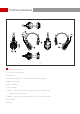
Product Interfaces 2 1 4 5 6 7 10 9 3 8 B B Headset Interfaces ① Power/Connection Indicator ② Microphone ③ USB Type-C Interface - For firmware upgrade, and headset pairing ④ Battery Compartment ⑤ Volume + Button ⑥ Volume - Button ⑦ A Button - Lights up when joined Group A, turns off when exited Group A; Long press for 5 seconds to pair ⑧ B Button - Lights up when joined Group B, turns off when exited Group B ⑨ Power Button ⑩ Speaker 3
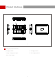
Product Interfaces ② ③ ① c c Charging Case Interfaces ① Charging Indicator ② Charging Contact ③ DC Charging Interface Orange: Charging in progress Green: Fully charged 4
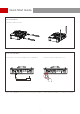
Quick Start Guide Set Up HUB Base Install the HUB antennas. Power Up HUB Base Press the Power Switch to turn on. Connect the 12V/2A DC Adapter to the HUB base. Note: The HUB Base can be powered using NP-F battery, V-Mount/G-Mount battery, or DC power supply.
Quick Start Guide Install Headset Battery Step 1: Slide the battery compartment cover lock Step 2: Open the cover Step 3: Place the batteries into the compartment and close the battery cover Turn On Headset Note: The indicator light stops flashing and turns to static green when the HUB Base and the Remote Headset(s) are successfully connected. Nameplate Power Switch Power up the Headset Mute/Unmute Microphone Mute/Unmute the headset’s microphone by moving the mic boom up/down.
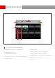
Quick Start Guide ⑧ ① Master ⑦ ② ⑥ ⑤ ④ ③ HUB Base Main Display Interfaces ① HUB Base configuration - Master/Slave ⑥ Headset status ② HUB Base battery level TALK: Headset is active to hear and talk ③ Headset signal strength MUTE: Headset is muted to hear only LOST: Headset lost connection with HUB Base ④ Headset battery level - turns red in low battery ⑦ Network connection status ⑤ Headset number ⑧ WiFi status 7
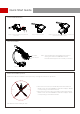
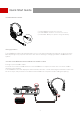
Quick Start Guide Headset Status Indicator ① FLASH GREEN: Headset disconnected ② STATIC GREEN: Headset connection successful ③ FLASH RED: Battery low, please change the battery Pairing Operation The HUB Base and Remote Headsets that come in one system package will auto pair up right out of box. Manual pairing is only required when there is a need for adding or changing headset or HUB base to the system. Connect the HUB Base and the Headset with a USB-C Cable. Pairing requires a USB-C cable.
Quick Start Guide Headset(s) Number Setting via HUB Base When re-pairing and numbering the headset, be sure to turn on all the headsets to avoid selecting duplicate numbers, which may lead to connection failure with other headsets. In case of wrong numbering of a headset, simply connect it to the HUB with the USB cable and operate the pairing and numbering process again. Cascade Connections Multiple intercom systems can be cascaded to expand the number of intercom headsets.
Quick Start Guide 4 Wire Settings After connecting the two systems with the network cable, configure each HUB Base’s line sequence by entering "4 Wire Settings" and selecting "Line sequence switching". Set the first HUB Base to “Standard mode” and the second HUB Base to “Cross mode”.
Quick Start Guide HUB Settings After connecting the two systems with the network cable, configure each HUB Base’s basic settings as Master or Slave device. Generally, the first system is set as Master Device, and the second one as Slave Device. In this case, you need to turn OFF the “Obtain IP address automatically” under “Network” settings on both the HUB Bases.
Quick Start Guide Group Settings The HUB Base supports A and B grouping settings. You can view the system’s current group setting by entering the Group menu on the HUB. To operate group settings, connect the computer and the HUB via the RJ45 interface using the network cable, and enter the Group settings menu. Or download the Solidcom APP on the mobile phone and connect to the HUB through WiFi to access the Group settings menu.
Quick Start Guide Open the browser on the computer and visit http://192.168.218.10 to enter the configuration page of the HUB. A & B Group Buttons on Headset(s) After entering Group setting on the HUB, the A and B Buttons on the connected headset will light up. The buttons light status indicates which group the headset has joined. Press the A or B Button on the headset to Join/Enter the corresponding group.
Parameters Range 350m (1000ft) Line-of-Sight Frequency Information Frequency band: 1.9GHz DECT (varies by country and region) Modulation mode: GFSK Transmit power:20.79dBm (varies by country and region) Frequency band: 5190MHz Modulation mode:OFDM Transmit power:9.10dBm Receiving sensitivity: <-90dBm Transmission Latency <35ms Battery Capacity 700mAh (2.66Wh) Li-Ion battery Headset Runtime Remote headset: ≈10h Charging Time ≈2.
Hollyland Products User Group HollylandTech HollylandTech Support@hollyland-tech.com www.hollyland-tech.
Statement: A l l co p y r i ghts belong to Shenzhen Hollyland Technology Co, . L T D. T r a d e m a r k Statement: Without the written approval of Shenzhen Hollyland Technology Co,.LTD, no organization or individual may copy or reproduce part or all of the content of the text without authorization, and may not disseminate it in any form. A l l re p r e s e ntations, informati o n , recommendations in this document d o no t co n s t itute warranties of any kind, ex p r es s or im p l i e d .
FCC Requirement Any changes or modifications not expressly approved by the party responsible for compliance could void the user’s authority to operate the equipment. This device complies with Part 15 of the FCC Rules. Operation is subject to the following two conditions: (1) this device may not cause harmful interference. (2) this device must accept any interference received, including interference that may cause undesired operation.