MARS 400S User Manual Version 1.2.
DESCRIPTION Thank you for purchasing Hollyland MARS 400S wireless HD video transmission system. The product uses the latest coding, decoding technology and 5G wireless transmission technology and can achieve ultra-low latency wireless video transmission. It has a transmission range over 400ft with a clean line of sight (LOS), supports up to 1080P 60Hz image resolution, and in the end achieves full HD HDMI/SDI video transmission.
PACKING LIST ① ⑤ ① ② ③ ④ ⑤ ⑥ ⑦ ⑧ ⑨ ② ⑥ ③ ⑦ ④ ⑧ Transmitter x1 Receiver x1 Antenna x5 Quick Guide x1 Cold Shoe x1 Expansion Accessory x1 DC Adapter x1 USB Type-C to Type-A OTG Adapter x1 C-Shaped Screw x1 ⑨ 2
TYPICAL SETUP HDMI/SDI IN HDMI/SDI OUT This wireless HD video transmission system uses the latest wireless communication technology and transmits ultra-low latency HD video. The transmitter supports both HDMI and SDI input, while the receiver supports both HDMI and SDI output. It is configurated with OLED display screen and supports iOS & Android App Monitoring.
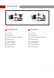
PRODUCT INTERFACES ① ① ② ② ⑥ ⑦ ⑧ ⑨ ③ ④ A ① ② ③ ④ ⑤ ⑥ ⑦ ⑧ ⑨ ⑩ ⑪ ⑫ B HDMI Input SDI Input OLED Display Screen DC Input 1/4 Screw Hole ⑪ A USB Type-C Interface Power Switch ⑤ ⑫ Fan Air Outlet Up ⑩ ⑫ Antenna Interface (RP-SMA Male) Menu/OK ④ ⑪ TRANSMITTER Down ③ ⑩ ⑤ ⑥ ⑦ ⑧ ⑨ B ① ② ③ ④ ⑤ ⑥ ⑦ ⑧ ⑨ ⑩ ⑪ ⑫ RECEIVER Antenna Interface (RP-SMA Male) Fan Air Outlet USB Type-C Interface HDMI Output SDI Output OLED Display Screen Down Menu/OK Up Power Switch DC Input 1/4 Screw Hole 4
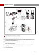
INSTALLATION ① ③ ② ④ ON VERTICAL INSTALLATION ① ② Install the antennas as demonstrated Secure the cold shoe with 1/4 screw hole at the bottom of the transmitter and mount it to the camera ③ Connect to a power supply (Compatible with NP-F970 or the same series of batteries) ④ Turn on the devices 5
INSTALLATION ① ④ ② ③ ⑤ ON HORIZONTAL INSTALLATION ① ② Install the antennas as demonstrated Connect the expansion accessary with the 1/4 screw hole at the bottom of the transmitter by a C-shaped screw ③ Secure the cold shoe with the 1/4 screw hole on the expansion accessary and install them on the camera ④ Connect to a power supply (Compatible with NP-F970 or the same series of batteries) ⑤ Turn on the devices 6
OLED DISPLAY ① ② ③ ④ 4E0657C ① ⑤ ⑥ ② ③ ④ ⑦ ⑧ 4E0657C A A ① ② ③ ④ ⑤ ⑥ ⑦ ⑧ TRANSMITTER Device ID Scene Mode USB Flash Detection Indicator Battery Status Device Number Signal Strength Channel Display Video Format ⑤ ⑥ ⑦ ⑧ B B ① ② ③ ④ ⑤ ⑥ ⑦ ⑧ RECEIVER Device ID Scene Mode USB Flash Detection Indicator Battery Status Signal Strength Device Number Channel Display Video Format 7
STATUS DESCRIPTION 4E0657C 4E0657C 4E0538D NO VIDEO A B 1. When the devices are disconnected, a cross “x” will appear above the signal strength bars on both the transmitter and the receiver. As shown in the above picture, device 1 is on connected status, while device 2 is on disconnected status. 2. As shown in the above picture, “NO VIDEO” will appear on the screen if there is no video input detected, and the video format will appear if there is a video input detected.
STATUS DESCRIPTION 4E0657C 4E0657C CH5 3. When the device detects a connection to a USB flash, the USB flash detection Indicator will light up. 4. When the voltage is too low, the low battery alarm will be triggered and the lowbattery icon will flash slowly. CAUTION When the receiver is not connected, it will not display the Channel ID. When the receiver is turned on, the channel ID will not be displayed before the receiver is connected with the transmitter.
QUICK GUIDE SCENE MODE IMAGE MODE BALANCE MODE SPEED MODE SCENE MODE SYSTEM SETTING VERSION INFO EXIT SYSTEM SETTING LANGUAGE PAIR RETURN VERSION INFO B0411DE0657C V1.0.2.0 RETURN TRANSMITTER 1. Long press the “MENU” button for about 3 seconds to enter the root menu interface. The root menu has “SCENE MODE”, “SYSTEM SETTING” and “VERSION INFO” options. 2. Select “SCENE MODE”, then click the “OK” button, you would be able to select “IMAGE MODE”, “BALANCE MODE” or “SPEED MODE”. 3.
QUICK GUIDE 1 √ 2 × 3√ 4√ 5√ 6√ 7√ 8 × 9 √ 10× 11√ 12√ 13√ CHANNEL SCAN SYSTEM SETTING VERSION INFO EXIT RETURN SYSTEM SETTING LANGUAGE PAIR RETURN VERSION INFO B0412D8F5CA5 V1.0.2.0 RETURN RECEIVER 1. Press the “MENU” button for about 3 seconds to enter the root menu interface. The root menu has “CHANNEL SCAN”, “SYSTEM SETTING” and “VERSION INFO” options. 2.
QUICK GUIDE CHANNEL CHANGE Press the channel button “UP/DOWN” on the transmitter or the receiver to change the current channel. Press “OK” to confirm the channel number, then the channel of the transmitter and the receiver will be synchronously and automatically changed. DEVICE UPGRADE 1. Copy the upgrade firmware to the root directory of a USB flash. 2. Insert the USB flash into the OTG adapter and connect it with the Type-C upgrade interface on the transmitter. 3.
QUICK GUIDE IOS & ANDROID APP MONIRTORING Android System Installation and Use 1. The application name is “HollyView”. It is available on Hollyland's official website and Android APP store. 2. Method No.1 Scan the QR code on the back of the transmitter then the APP will be automatically connected to the device. Enter the main interface and you would be able to monitor the video shot on the camera. Method No.2 Input the device’s ID number and manually connect the device.
PARAMETERS Transmitter Receiver HDMI Input (Type A Female) SDI Input 2 Antenna Interfaces (RP-SMA Male) DC Input, Type-C USB HDMI Output (Type A Female) SDI Output 2 Antenna Interfaces (RP-SMA Male) DC Input, Type-C USB Supply Interface 6~16V DC 6~16V DC Power Consumption <11W <6W Weight 192g 189g Size 112*65*23.5mm (L*W*H) External antennas and battery plate excluded 112*65*23.
FAQ CONNECTION ISSUES 1. Check and make sure that the power supply works fine on both the transmitter and the receiver. 2. If the device displays with the low-battery sign, change or charge the battery in time. 3. Try to change to another channel and to connect the devices again for there might be interference for the current channel. 4. Re-pair the devices. 5. Check if the antennas on the transmitter and receiver are correctly installed. DISPLAY ISSUES 1.
FAQ LIMAGE LOW QUALITY ISSUES 1. Set “SCENE MODE” to “IMAGE MODE”. 2. Check if the HDMI/SDI IN or OUT cables are correctly connected. 3. Make sure both the transmitter and the receiver are installed at least 1.5m above the ground. 4. Check the signal strength status. If it is with only 1 bar signal, it means that the signal strength is very weak. In this case, change the channel or shorten the distance between the devices. LAPP CONNECTION ISSUES 1. Check the number of connected APP devices.
HollylandTech HollylandTech HollylandTech sales@Hollyland-tech.com www.hollyland-tech.