TDM A U D I O 24CX-2 24CX-3 24CX-4 ELECTRONIC CROSSOVER OWNER’S MANUAL TDM AUDIO INC. 7270 BELLAIRE AVE. NORTH HOLLYWOOD, CA 91605 (818) 765-6200 TDMAUDIO.
IMPORTANT! *** Read Before Using *** CAUTION: The following must be observed to prevent malfunctioning and/or possible equipment damage. • Before plugging the unit into the main AC line, make sure that all of the equipment following the crossover output lines is turned off or all of the inputs are turned down. • Never change the frequency range switch from the x10 to x1 position (or vice versa) with the crossover output levels passing signal. Transients can result and speaker damage is possible.
Table of Contents INTRODUCTION .......................................................................................................................................................4 CROSSOVER FUNDAMENTALS .....................................................................................................................................4 CROSSOVER TERMINOLOGY .......................................................................................................................................
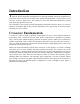
Introduction T hank you for purchasing the TDM 24CX series electronic crossover. These units are made from the finest components and engineered to exacting standards. Precision components are used in all critical circuitry for the finest sonic quality and performance. To get the most out of your new crossover, please take a few minutes to review this manual and familiarize yourself with the proper operation of the unit.
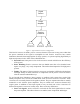
Signal Source Power Amplifier Passive Crossover Low Transducer Mid Transducer High Transducer Figure 1 - Typical Passive Crossover Configuration This kind of crossover is called a passive crossover because it does not use any power other than the power contained in the signal to accomplish its task. Passive crossovers have certain limitations that make them inappropriate for large systems, or systems requiring high fidelity at high sound pressure levels.
• External Power: Passive crossovers are simply inserted between the amp and the speaker components. Active crossovers must be plugged into an electrical outlet in order to work. • Higher Typical Rolloff Rates: Passive crossovers typically roll off at rates from 6 to 12 dB per octave. Most modern active crossovers have rates of at least 24 dB per octave (more about rolloff rates later). • More Power Amplifiers: Active crossovers break the signal into many different bands before the power amplifiers.
result in a greater overall efficiency of the system by making sure a band of frequencies is always reproduced by the speaker components that are most efficient at reproducing it. How Crossovers Work To divide a range of frequencies into two or more smaller ranges, a crossover uses filter circuits. A filter is simply a circuit that lowers the levels of unwanted frequencies in a signal.
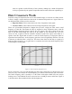
5 0 -5 -10 Gain (dB) -15 -20 -25 -30 -35 -40 2780 2660 2540 2420 2300 2180 2060 1940 1820 1700 1580 1460 1340 1220 980 1100 860 740 620 500 380 -45 Frequency (Hz) Figure 4 - 24 dB per Octave Filter Curve To make a 2-way crossover, we feed the same signal into a high-pass filter and a low-pass filter with the same cutoff frequency. This is called the crossover frequency. The output of the highpass filter is the high output of the crossover.
The crossover frequency of 1000 Hz is where the two lines on this graph cross over each other. In crossovers with three or more output bands, there are two filters for each of the middle bands. A low-pass filter rolls off frequencies above a certain cutoff point. A high-pass filter rolls off frequencies below a certain cutoff point. This leaves a band of frequencies in the middle. These middle bands have two different cutoff points. Figure 6 shows the responses of the three bands of a three-way crossover.
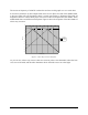
Mounting the Unit in a Rack T DM 24CX series crossovers can be mounted in any standard 19” rack. Each TDM 24CX series crossover takes up one rack space. To make mounting easier, lay the rack on its back with the equipment front panels facing up. Remove any rack screws from the part of the rack where you are planning to mount the crossover. Position the TDM 24CX series crossover in the rack as desired. Make sure the mounting holes in the crossover line up with the screw holes in the rack rails.
Hooking Up the Crossover O nce your TDM crossover is installed in the rack, you are ready to hook it up to your equipment. Of course, the method used to hook up any crossover depends on how it will be used. We will try to give you the basics in this manual, but you may need to tailor the methods described here to your particular application. What You’ll Need To connect your 24CX series crossover to your equipment, you will need the following.
It is very important that both pins 1 and 3 are wired to the sleeve. Some adapters leave pin 3 floating, and with TDM crossover units this will cause problems. If you have a TDM 24CX series crossover with ¼” connectors, you may connect directly to other equipment using ¼” connectors whether the other equipment is balanced or not.
channels to link them together and form one three-way channel. This switch may be found on the rear of the unit between the channels. It is recessed into the chassis through a small, square hole, and you might need to use a small screwdriver to press it. When it is in the in position, the channels are linked. When it is in the out position, the channels are not linked.
Operating the Crossover O nce you have mounted your TDM 24CX series crossover in a rack and connected all of the cables, the unit is ready for operation. At this time, make sure the input levels on the front of the crossover and the input levels of the amplifiers are all the way down. Next, turn all equipment on. It is always best to turn the equipment on in the order of the signal path from input to output and to turn it off in exactly the reverse order.
Channel One (or Three) Input Level Input Level Channel One (or Three) Crossover Frequency High-To-Mid Crossover Frequency Channel One (or Three) Range Switch High-To-Mid Range Channel One (or Three) High Output Level High Output Level Channel One (or Three) Low Output Level Not Used Channel Two (or Four) Input Level Not Used Channel Two (or Four) Crossover Frequency Mid-To-Low Crossover Frequency Channel Two (or Four) Range Switch Mid-To-Low Range Channel Two (or Four) High Output Level Mid
Checking the Hookup It is critical that the crossover is connected and adjusted correctly before use. To avoid speaker damage, we recommend checking your hookup and settings using the following method. 1. Make sure the input level and all output levels on the crossover are down. Adjust the crossover frequencies according the recommendations of your speaker manufacturer. 2. Turn on the amplifiers and raise their gains about halfway up (leaving the levels on the crossover all the way down). 3.
Adjusting the Output Levels Start with the input levels at 0 dB (unity gain). After the rest of the system has been dialed in (amplifier gains and output levels), the input levels can be fine tuned. Feed a lower-than-normal level signal from your signal source into the system. You want to make sure that you set it up so you have room to spare.
TDM Option Cards T he TDM 24CX series crossovers have internal connectors for option cards. A variety of different option cards is available from TDM. Plugging a card into the connector inserts the circuitry on the card between a crossover section output and the output of the unit. The most common card to use for this application is the high-pass filter card. This card is used on the lowfrequency section of the crossover to remove subsonic frequencies from the output.
Optional Output Limiters T he TDM 24CX series crossovers can be ordered with output limiters. These let you set the maximum level for each crossover output. Limiters are used to help protect speaker components and ears from damage by excessive levels. Levels above the preset threshold are reduced automatically by the limiter circuit.
Troubleshooting and Support T his section details various problems that you might encounter when using your crossover, and the possible causes and solutions. It also tells how to contact TDM when you need service or support for your 24CX series crossover. No Signal Output If you are getting a signal from some of the frequency bands, but one or more of them is not working, check the cables and hookups for the band(s) in question.
is the cause of the distortion. If none of the signal processing units in the chain is causing the distortion, then either it is present in the signal source, or there is a problem with your speaker system, amplifiers, or crossover. If you determine that the TDM 24CX series crossover is the cause of a distortion problem, make sure that the unit is plugged into a proper power source. Read the back panel of the unit for the correct supply voltage and frequency (US models are set up for 110 VAC at 60 Hz).
two different grounds. The problem is most often caused by a single piece of equipment grounded to two different power sources that are located some distance apart. For example, a mixing console is plugged into a grounded outlet at the back of an auditorium, and the power amplifiers are plugged into a different outlet 100 feet away at the stage. The mixing console is connected by shielded cable to the amplifiers and the shield is grounded.
Specifications Frequency Response Low Frequency Output High Frequency Output Total Harmonic Distortion RL > 2 kohms Low Frequency Output High Frequency Output Maximum Output Level RL > 2 kohms +0-0.5 dB 10 Hz +0-1.0 dB 20 kHz CONSTANT-DIECTIVITY CORRECTION 20.000 10.000 <0.01% THD <0.02% THD 0.0 -10.00 +21 dBu (6.2 volts) @<.05% THD Maximum Voltage Gain 6 dB Constant-Directivity Correction +3 dB @ 3.5kHz rising at 6dB/octave to 22.