Holy Stone Enterprise Co., Ltd. CERAMIC CAPACITOR CATALOG www.holystone.com.tw www.holystonecaps.
Introduction The Company Holy Stone Enterprise Company Ltd. (Holy Stone) was established in June of 1981 as an agent and distributor of electronic components. In 1994, with technology and cooperation from a Japanese partner, Holy Stone began manufacturing Multi-layer Ceramic Capacitors. Today, Holy Stone is recognized as an industry leader in application specific ceramic capacitors. Holy Stone integrates active and passive component distribution with significant manufacturing capabilities.
Contents Holy Stone CONTENTS Component Quick Reference ------------------------------------------ 2 Capacitance Availability Guide ----------------------------------------- 3-4 Products Series ----------------------------------------------------------- 5-47 Packing Information ------------------------------------------------------ 48-51 General Information ------------------------------------------------------- 52-53 Precautionary Information ---------------------------------------------- 54-57
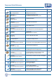
Component Quick Reference Holy Stone Product Series Application Page HVC Series -High Voltage Capacitors For Power Circuits (Backlight Inverter, DC to DC,…) 5-8 SCC Series -Safety Capacitors For Isolation and Protection Circuits (UL, EN132400 Class X2/Y3, X1/Y2, and X2) 9-10 TCX Series -Trigger Capacitors For DSC Strobe Circuits 11-12 LDC Series -Low Distortion Capacitors For Oscillation and Filter Circuits 13-14 NCC Series -Normal Chip Capacitors For Decoupling Circuits 15-16 HCC Series -
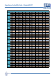
Capacitance Availability Guide – Standard MLCC Vdc NP0 6.3V X7R X5R NP0 10V X7R X5R NP0 16V X7R X5R NP0 25V X7R X5R NP0 35V X7R X5R NP0 50V X7R X5R NP0 100V X7R X5R NP0 200V X7R X5R NP0 250V X7R X5R NP0 500V X7R X5R NP0 630V X7R X5R NP0 1KV X7R X5R NP0 2KV X7R X5R NP0 3KV X7R X5R NP0 4KV X7R X5R NP0 5KV X7R X5R 0201 0402 0603 0805 1206 1210 100nF 470nF 10uF 2.2uF 22uF 10uF 47uF 22uF 100uF 100uF 2.2uF 10uF 3.3nF 1uF 4.7uF 3.3nF 1uF 2.2uF 10uF 22uF 10nF 10uF 22uF 10nF 4.
Capacitance Availability Guide – Safety Capacitors Holy Stone SMD Capacitors Vac X2/Y3 X1/Y2 X2 1808 1812 2208 2211 2220 2825 250Vrms NP0 2.0pF–1nF N/A N/A N/A N/A N/A 250Vrms SL 220pF-1nF N/A N/A N/A N/A N/A 250Vrms X7R 150pF–2.2nF 330pF–4.7nF N/A N/A N/A N/A 250Vrms NP0 2.0pF–330pF 2.0pF-680pF 2.0pF-330pF 2.0pF-1nF 2.0pF-1.2nF N/A 250Vrms X7R 150pF-1nF 130pF-1nF 36pF-1nF 68pF-2.7nF 101pF-4.
HVC Series - High Voltage Capacitors Holy Stone Multilayer Ceramic Chip Capacitors [ High Voltage NP0 and X7R Capacitors ] HVC Series Holy Stone high voltage products are designed and manufactured to meet the general requirements of international standards. The product offering is well suitable for commercial and industrial applications and includes NP0 (C0G), SL, and X7R characteristics in sizes 0603 to 2225 and with working voltages up to 5KV.
HVC Series - High Voltage Capacitors Holy Stone Dimensions BW Unit : mm [inches] TYPE B L 1.60 0.10 ± [.063±.004] 2.00±0.20 [.079±.012] 3.20±0.30 [.126±.012] 3.20±0.30 [.126±.012] 4.60±0.30 [.181±.012] 4.60±0.30 [.181±.012] 4.60±0.30 [.181±.012] 5.70±0.40 [.220±.016] 5.70±0.40 [.220±.016] 0603 0805 T 1206 1210 W L 1808 1812 1825 2220 2225 W 0.80 0.10 [.031 ±.004] 1.25 0.20 ± ± [.049±.012] 1.60±0.20 [.063±.012] 2.50±0.20 [.098±.012] 2.00±0.20 [.079±.008] 3.20±0.30 [.126±.012] 6.35±0.40 [.250±.
HVC Series - High Voltage Capacitors Holy Stone NP0 Size Rated Voltage 2225 100V 200V 250V 500V 630V 1KV Capacitance Range 2R0 3R3 3R9 5R0 8R2 100 120 150 180 220 270 330 390 470 560 680 820 101 121 151 181 221 271 331 391 471 561 681 821 102 122 152 182 222 272 332 392 472 562 682 822 103 123 153 183 223 273 333 393 473 563 683 Temperature Characteristic DDD Capacitance Range – X7R 100Vdc to 1KVdc Size 0603 Rated Voltage 100V 100V 200V 0805 250V 500V 1KV Capacitance Range 151 181 221 271 3
HVC Series - High Voltage Capacitors Holy Stone Capacitance Range 2KV Rated Voltage NP0 1206 1808 1812 2KV 2KV 2KV Temperature Characteristic Size Rated Voltage X7R 1206 1210 1808 1812 1825 2220 2225 2KV 2KV 2KV 2KV 2KV 2KV 2KV Capacitance Range 2R0 3R3 3R9 5R0 8R2 100 120 150 180 220 270 330 390 470 560 680 820 101 121 151 181 221 271 331 391 471 561 681 821 102 122 152 182 222 272 Size D D D D D D D D D D D D D D D/E D/E D/E D/E D/E D/E D D D D D D D D D D D D D D D D D D E/F E/F E/F E/F E/
SCC Series - Safety Capacitors Holy Stone Multilayer Ceramic Chip Capacitors [ Safety Capacitors – X2, X2Y3 & X1Y2 ] SCC Series Rated up to 305Vac The SCC series X2, X2/Y3 & X1/Y2 rated at 250Vrms and X2 rated at 305Vrms safety capacitors are designed specifically for use in modem, facsimile, telephone and other electronic equipment. These parts are compliant to EN132400-14, IEC60384-14 and UL60950-1 standards. These capacitors are available in NP0 (C0G) and X7R dielectrics.
SCC Series - Safety Capacitors Holy Stone Summary of Specifications Rated Voltage AC 250Vrms and AC 305Vrms NP0 : < 30ppm/ , -55 ~ +125 (EIA Class ) X7R : < 15% , -55 ~ +125 (EIA Class ) X2/Y3 : 2.0pF ~ 2700pF , X1/Y2 : 2.0pF ~ 4700pF X2 – 250Vrms : 150pF ~ 56nF X2 – 305Vrms : 150pF ~ 33nF NP0 : Q 1000 , X7R : D.F. 2.5% -55/125/21 10G X Capacitor : Applied Voltage 1075Vdc(4.3Ur) Y Capacitor : Applied Voltage 1500Vac Y3 : 2.5KV (Compliant to IEC 60950) , X2 : 2.
TCX Series - Trigger Capacitors for Strobe Holy Stone Multilayer Ceramic Chip Capacitors [ Trigger Capacitors for Strobe ] TCX Series The TCX series is specifically designed with a proprietary material for discharge applications such as strobe circuit applications. The unique properties of the X7E material, and the design of the TCX series, make them suitable for any discharge application which requires the capacitor to have a good damping characteristic.
TCX Series - Trigger Capacitors for Strobe Holy Stone Characteristics R-C Charge Curv e Damping (Trigger) Properties 300 4000 TCX/1206/223K/630V 3000 X7R/1206/223K/630V 250 2000 Voltage (V) Trigger Voltage (Vp) 5000 1000 0 -1000 200 150 100 TCX/1206/223K/630V -2000 50 -3000 X7R/1206/223K/630V 0 -4000 0 1 Application 2 3 4 5 6 Time (µs) 7 8 9 0 10 1 2 3 4 Time (sec.) 5 6 7 Example of Circuit DSC Strobe Circuit Trigger Cap.
LDC Series - Low Distortion Capacitors Holy Stone Multilayer Ceramic Chip Capacitors [ Low Distortion Capacitors ] LDC Series Low Distortion Capacitors (NP0/X7R Hybrid) Features Applications Suitable for telecommunication (ADSL, Modem, …), power (inverter for oscillation circuit) and audio circuit Small size & high capacitance Ultra stable T/C for a Class ll Excellent Bias, high temperature stability & low Tan High breakdown voltage Replacement for Film Capacitors RoHS compliant δ
LDC Series - Low Distortion Capacitors Holy Stone Characteristics Temperature Capacitance Coefficient Impedance/ESR & Frequency 20.0 100 LDC 1206/103 10.0 ESR - LDC/1206/103 ESR - Film Cap /1206/103 10 5.0 (ohm) dC/C (%) Z - LDC/1206/103 Z - Film Cap 1206/103 X7R 1206/103 15.0 0.0 1 -5.0 -10.0 0.1 -15.0 -20.0 -55 -45 -35 -25 -15 -5 5 Temperature Temperature Application 0.01 0.1 15 25 35 45 55 65 75 85 95 105 115 125 ℃ 1 10 100 1000 Frequency (MHz) Example of Circuit 1.
NCC Series - Normal Chip Capacitors Holy Stone Multilayer Ceramic Chip Capacitors [ Normal Chip Capacitors – NP0,X7R,X5R,Y5V ] NCC Series Standard Multilayer Ceramic Chip Capacitors are available in a full range of sizes and temperature coefficients, with voltage ratings from 6.3V to 50V.
NCC Series - Normal Chip Capacitors Holy Stone Capacitance Range 16V S S S S S S S S S S S S S S S S S S S S S S S S 25V S S S S S S S S S S S S S S S S S S S S S S S S 0402 50V OOOOOOOOOOOOOOOOOOOOOOOOOOOOOOOO 0603 50V B B B B B B B B B B B B B B B B B B B B B B B B B B B B B 0805 50V B B B B B B B B B B B B B B B B B B B B B B B B Dielectric Size Rated Characteristic Voltage Capacitance Range 101 121 151 181 221 271 331 391 471 561 681 102 122 152 182 222 272 332 392 472 562 682 822 103 1
HCC Series - High Capacitance MLCC Holy Stone Multilayer Ceramic Chip Capacitors [ High Capacitance MLCC – 1.
HCC Series - High Capacitance MLCC Holy Stone Capacitance Range X7R (X) Series Size 0603 1206 0805 1210 1812 2220 Code 6.3V 10V 16V 25V 6.3V 10V 16V 25V 35V 50V 6.3V 10V 16V 25V 35V 50V 10V 16V 25V 35V 50V 25V 50V 50V 105 B B B B D D D D D D D D D/E D/E D/E D/E D D D D E F F F 155 D F 225 B B D D D D D D E E E E E E F F F F F F F F 335 D D E E E F 475 D D D D E E E E E E F F F F F F F F 106 D D D E E E E F F F F G G G 226 E E G G G X6S (S) Series Size 0402 0603 0805 1206 1210 Code 6.3V 6.
HCN Series - High Cap NP0 Holy Stone Multilayer Ceramic Chip Capacitors [ High Cap.
HCN Series - High Cap NP0 Holy Stone Characteristics Z/ESR & Frequency Temperature Capacitance Coefficient 100000 5000 ESR-MLCC NPO 1812/683 NPO-1812/683 Film-1812/683 3000 1000 2000 Z- Film Cap 1812/683 ESR- Film Cap 1812/683 100 Ohm dC/C (ppm) Z- MLCC- NPO 1812/683 10000 4000 1000 0 10 -1000 1 -2000 0.1 -3000 0.01 -4000 0.001 -5000 -55 -45 -35 -25 -15 -5 5 0.
HCX Series - High Cap X7R Holy Stone Multilayer Ceramic Chip Capacitors [ High Cap.
HCX Series - High Cap X7R Holy Stone Characteristics Impadance/ESR & Frequency Ripple Current 1000 100 ESR-1812/155 10KHz -1812/155 Z 100KHz-1812/155 Chip Surface Temp.(∆C) -1812/155 (ohm) 10 1 0.1 300KHz-1812/155 100 10 1 0.01 1 10 Application 100 1000 Frequency (KHz) 10000 0 100000 0.5 1 1.5 2 2.5 Ripple Current (Arms) 3 3.5 Example Circuit DC-DC Converter Filter Isolation Transformer Dimensions BW Unit : mm [inches] B TYPE 1210 T 1812 1825 W L 2220 2225 L 3.
SAC Series - Tip & Ring Capacitors Holy Stone Multilayer Ceramic Chip Capacitors [ Tip & Ring Capacitors ] SAC Series Telephone lines use a DC voltage of 48 volts and pass the subscriber’s AC signal pulse of 15 to 25Hz, at 70 to 90Vrms. These MLCC Tip & Ring capacitors replace bulky leaded film capacitors and offer excellent frequency response, low ESR, and improved temperature characteristics. Ideal for telecommunication and modem applications.
SAC Series - Tip & Ring Capacitors Holy Stone Dimensions BW B TYPE 0805 T 1206 1210 1812 W 2220 L L 2.00 0.20 ± 3.20±0.30 [.126±.012] 3.20±0.30 [.126±.012] 4.60±0.30 [.181±.012] 5.70±0.40 [.220±.016] [.079±.008] W 1.25 0.20 [.049 ±.008] 1.60 0.20 Unit : mm [inches] B (min) BW (min) 0.70 0.20 T (max) 1.45 ± ± [.063±.008] 2.50±0.20 [.098±.008] 3.20±0.30 [.126±.012] 5.00±0.4 [.197±.016] [.057] [.028] [.008] 1.80 1.50 0.30 [.071] [.059] [.012] 2.60 1.60 0.30 [.102] [.063] [.012] 3.
HBC Series - Low-Loss, High Frequency Capacitors Holy Stone Multilayer Ceramic Chip Capacitors [ Low-Loss, High Frequency Capacitors ] HBC Series Features Applications High frequency pulse circuits Lighting ballast snubber circuits DC-DC converters High dv/dt rating Low stable ESR at high frequency Ultra stable NP0 performance Suitable for solder wave and reflow soldering RoHS compliant High peak to peak voltage capability Summary of Specifications ℃ ~ +125 ℃ Operation Tempera
HBC Series - Low-Loss, High Frequency Capacitors Holy Stone Characteristics Peak to Peak Voltage To convert a DC voltage rating to maximum Peak to Peak voltage, a conversion factor of 1.25:1 should be used. Example: 500VDC rating = 500/1.25 = 400V Peak to Peak voltage, where Peak to Peak is defined as below. AC Voltage Pulsed Voltage 0V DC + AC Voltage DC + Pulsed Voltage 0V = Peak to Peak voltage Unit : mm [inches] Dimensions BW B TYPE T 1206 1210 W L W 3.20 0.30 1.60 0.2 [.126 .012] [.063 .
HTC Series - High Temperature Capacitors Holy Stone Multilayer Ceramic Chip Capacitors High Temperature Capacitors HTC Series [ X8R rated to +150°C] Applications Features Suitable for automotive, oil exploration and other demanding high temperature environments and applications Instrumentation and other equipment circuit operating at high temperatures Rated voltages from 25Vdc to 250Vdc Stable temperature coefficient of ±15% at high temperature (up to 150 ℃) Fully RoHS compliant Availab
HTC Series - High Temperature Capacitors Holy Stone Characteristics X8R-1206 / 100nF 20.0 15.0 10.0 dC/C (%) 5.0 0.0 -5.0 -10.0 -15.0 -20.0 -25.0 -55 -40 -25 -10 5 20 35 50 65 80 95 110 125 Dimensions BW 140 150 Unit : mm [inches] B TYPE 0603 T 0805 1206 W 1210 L 1.60 0.10 ± [.063±.004] 2.00±0.20 [.079±.008] 3.20±0.30 [.126±.012] 3.20±0.30 [.126±.012] W 0.80 0.10 [.031 ±.004] 1.25 0.20 [.049 ±.008] 1.60 0.20 ± ± ± [.063±.008] 2.50±0.20 [.098±.008] T (max) 0.95 B (min) 0.
RFC Series - Radio Frequency Capacitors Holy Stone Multilayer Ceramic Chip Capacitors [ Radio Frequency Capacitors ] RFC Series Features High Q value & Low ESR at high frequency Ultra stable NP0 performance Ultra miniature size 0603 to 1111 Low capacitance with tight tolerance RoHS compliant Applications Radio frequency ■ Impedance matching circuit ■ Resonant circuit ■ Coupling circuit ◆ RF Modules, VCO, BPF, DUP, PA, etc. ◆ Cellular Phone, Bluetooth, Wireless LAN, etc.
RFC Series – Radial Frequency Capacitors Holy Stone Characteristics 0505-ESR vs Frequency 1111-ESR vs Frequency 0505-Q Factor vs Frequency 1111-Q Factor vs Frequency Dimensions BW Unit : mm [inches] B TYPE T 0603 0505 0805 W L 1206 1210 1111 L 1.60 0.10 ± [.063±.004] 1.40±0.25 [.055±.010] 2.00±0.20 [.079±.008] 3.20±0.30 [.126±.012] 3.20±0.30 [.126±.012] 2.80±0.40 [.110±.016] - 30- W 0.80 0.10 [.031 ±.004] 1.40 0.25 [.055±.010 ] 1.25 0.20 [.049 ±.008] 1.60 0.20 [.063 ±.008] 2.50 0.20 [.
RFC Series – Radio Frequency Capacitors Holy Stone Capacitance Range Size Voltage COG 0603 250V 0505 250V 0805 R10 R20 R30 R40 R50 R60 R70 R80 R90 1R0 1R1 1R2 1R3 1R5 1R6 1R8 2R0 2R2 2R4 2R7 3R0 3R3 3R9 4R7 5R6 6R8 8R2 100 120 150 180 220 270 330 390 470 560 680 820 101 121 151 181 221 271 331 391 471 561 681 821 102 Capacitange Range T.C. 250V 100V 1206 200V 500V 100V 1210 200V 500V 50V 100V 1111 200V 300V 500V Tolerance ± 0.05pF ±0.075pF ±0.1pF ± 0.
LCC Series - Large Size Multilayer Ceramic Chip Capacitors Holy Stone Multilayer Ceramic Chip Capacitors [ Large Size Ceramic Chip Capacitors ] LCC Series Features Applications Optimized internal designs offers the highest voltage rating (up to 8KVdc) Capacitance range from 470pF to 33uF and sizes from 1515 to 7565 Available with proprietary surface coating for arc prevention Available with flexible termination (Super Term) to minimize the effects of mechanical stress High reliability scre
LCC Series - Large Size Multilayer Ceramic Chip Capacitors Holy Stone Dimensions TYPE BW 1515 B 2520 T 3530 3640 4540 W 5550 L 6560 7565 L 3.80 0.50 ± 6.35±0.50 [.25±.020] 8.90±0.50 [.35±.020] 9.20±0.50 [.36±.020] 11.5±0.50 [.45±.020] 14.0±0.50 [.55±.020] 16.5±0.50 [.65±.020] 19.0±0.50 [.75±.020] [.15±.020] W 3.80 0.50 [.15 ±.020] 5.00 0.50 ± ± [.20±.020] 7.60±0.50 [.30±.020] 10.2±0.50 [.40±.020] 10.2±0.50 [.40±.020] 12.7±0.50 [.50±.020] 15.3±0.50 [.60±.020] 16.5±0.50 [.65±.020] T (max) 3.
RDC Series - Radial Dipped Ceramic Capacitor Holy Stone Radial Dipped Ceramic Capacitors [General Used Capacitors – 6.
RDC Series - Radial Dipped Ceramic Capacitor Holy Stone Unit : mm [inches] Structure & Standard Dimensions TYPE Epoxy MLCC Solder [0.177] [0.217] CK 4.5 5.5 [0.177] [0.217] [0.098] ED T W 223 W EK FD T L FK 223 GD GK ℓ Φd ℓ Φd WD WK F 25.0 T (max) 2.5 DK L [0.984] 5.0±1.0 W (max) 5.5 4.5 5.5 2.5 [0.177] [0.217] [0.098] Lead Wire K.Type [.098 ±.020] 2.5 L (max) 4.5 DD D.Type ℓ (min) 25.0 [0.098] F 2.5±0.5 CD F UD 4.5 5.5 2.5 [0.177] [0.217] [0.098] 5.
HDC Series - High Voltage Ceramic Disc Capacitors Holy Stone Ceramic Disc Capacitors [ High Voltage Disc Capacitors ] HDC Series – 1KVdc to 6KVdc HDC Series (ceramic disc capacitors) are ideal for use in general electronic products with voltage ratings from 1KV to 6KV.
HDC Series - High Voltage Ceramic Disc Capacitors Holy Stone Dimensions S Type D Type s s Code D 8D 6KV 8D 6KV F D T D T DR G G T DR DR G L L F Dimension Φ20.5mm max. 5.0±1.0 7.50±1.5 10.0±2.0 12.5±2.0 mm mm mm mm 0.5±0.1mm / 0.6±0.1mm / 0.8±0.1mm 8.0mm max. 4.0mm max. F Leakage Current Characteristics ( Typical Reference) NPO/SL -6KVdc Y 5P -3KVdc 0.20 1.20 leakage current(mA) leakage current(mA) SL/47pF/6KV 0.16 0.12 SL/10pF/6KV 0.08 NP0/2pF/6KV 0.04 0.00 1.
HDC Series - High Voltage Ceramic Disc Capacitors Holy Stone Ceramic Disc Capacitors [ High Voltage Disc Capacitors ] HDC Series – Low Loss / Low Dissipation The series (R type) used in electronic product and with voltage ratings from 1KV to 3KV. Ideal for use on high frequency pulse circuits such as horizontal resonance circuits for CTV and snubber circuits for switching power supplies.
HDC Series - High Voltage Ceramic Disc Capacitors Holy Stone Dimensions S Type D Type s s Code D 471K 1KV 471K 1KV F D T D T DR G G T DR DR G L L F Dimension Φ20.5mm max. 5.0±1.0 7.50±1.5 10.0±2.0 12.5±2.0 mm mm mm mm 0.5±0.1mm / 0.6±0.1mm / 0.8±0.1mm 8.0mm max. 4.0mm max.
HDC Series - High Voltage Ceramic Disc Capacitors Holy Stone Ceramic Disc Capacitors [ Ultra High Voltage Disc Capacitors ] HDC Series – over 10KVdc HDC Series (ceramic disc capacitors) are ideal for use in general electronic products with voltage ratings over 10KVdc.
HDC Series - High Voltage Ceramic Disc Capacitors Holy Stone Dimensions D Type T D Dimension Code s 102M 12KV D Type D Please contact Holy Stone 10.0±2 mm F DR G L 12.5±2 mm G 0.8±0.1mm max. T Please contact Holy Stone DR 5.0mm max. F Temperature Capacitance Coefficient & DC Bias ( Typical Reference) Y5S Temperature Capacitance Coefficient Y5S DC Bias Characteristic 30.0 10 20.0 0 dC/C (%) dC/C (%) 10.0 0.0 -10.0 -10 -20 -20.0 -30 -30.0 -40.
HDC Series - High Voltage Ceramic Disc Capacitors Holy Stone Caution (1) Operating Voltage: When DC-rated capacitors are to be used in AC or ripple current circuits, be sure to maintain the Vp-p value of the applied voltage or the Vo-p which contains a DC bias within the rated voltage range. When the voltage is applied to the circuit, starting or stopping may generate an irregular voltage for a transit period because of resonance or switching.
HDC Series - High Voltage Ceramic Disc Capacitors Holy Stone (6) Soldering When soldering this product to a PCB/PWB, do not exceed the solder heat resistance specification of the capacitor. Subjecting this product to excessive heating could melt the internal solder joint and may result in thermal shock that can crack the ceramic element. When soldering capacitors with a soldering iron, it should be performed in following conditions. Temperature of iron-tip: 400 degrees C. max.
SDC Series - Safety Disc Capacitors Holy Stone Ceramic Disc Capacitors [ Safety Disc Capacitors – X1Y1& X1Y2] SDC Series This specification applies to the following Safety Standards that are recognized for Ceramic Capacitors used in Electronic Appliances.
SDC Series - Safety Disc Capacitors Summary of Specifications ℃ Operation Temperature Holy Stone ℃ -25 ~ +125 X1:440 VAC / Y1:250 VAC : 4000VAC for 1 minute X1:440 VAC / Y1:400 VAC : 4000VAC for 1 minute X1:400 VAC / Y2:250 VAC : 2600VAC for 1 minute X1:440 VAC / Y1:250 VAC : 2pF to 4700pF X1:440 VAC / Y1:400 VAC : 2pF to 4700pF X1:400 VAC / Y2:250 VAC : 2pF to 10,000pF Class I , NP0/SL : Q ≥ 300 at 1MHz/1Vrms Class II , Y5P : DF ≤ 2.5% , Y5U/Y5V : DF ≤ 5.0% at 1KHz/1Vrms 10,000M min.
SDC Series - Safety Disc Capacitors Holy Stone Caution (Rating) (1) Operating Voltage Be sure to maintain the Vp-p value of the applied voltage or the Vo-p which contains a DC bias within the rated voltage range. When the voltage is started to apply to the circuit or it is stopped applying, the irregular voltage may be generated for a transit period because of resonance or switching. Be sure to use a capacitor within rated voltage containing this irregular voltage.
SDC Series - Safety Disc Capacitors Caution (Storage and operating condition) Holy Stone The insulating coating of capacitors does not form a perfect seal; therefore, do not use or store capacitors in a corrosive atmosphere, especially where chloride gas, sulfide gas, acid, alkali, salt are likely to be present. And avoid exposure to moisture.
Packing Information Holy Stone Multilayer Ceramic Chip Capacitor Bulk Packing Standard packing 10Kpcs/pack, others according to customers’ request. Tape Packing Paper Tape Embossed Tape Top Cover Tape Top Cover Tape Embossed Carrier Tape Carrier Tape Bottom Cover Tape Empty Section 40mm min. Empty Section 20mm min. Chip Section 400mm min. Drawing Direction Material And Quantity (¢180mm) Chip Size (EIA Code) 0201 0402 0603 0805 L 0.6 1.0 1.6 2.0 Dimension (mm) W 0.3 0.5 0.8 1.25 1206 3.
Packing Information Holy Stone Tape Dimensions and Specifications Paper Tape Pitching Hole Chip Cavity I F A G B C t A B C D E F G H I t 0201 0.37±0.1 0.67±0.1 4.00±0.1 2.0±0.05 2.00±0.1 1.75±0.1 3.5±0.05 8.00±0.3 ¢1.5+0.1/-0 1.1 max. 0402 0.61±0.1 1.20±0.1 -- --> -- --> -- --> -- --> -- --> -- --> -- --> -- --> D H E 0603 1.10±0.2 1.90±0.2 0805 1.50±0.2 2.30±0.2 4.00±0.1 -- --> 1206 1.90±0.2 3.50±0.2 Unit:mm 1210 2.90±0.2 3.60±0.
Packing Information Holy Stone Reel Dimensions Unit:mm E A B C D E W t r C B D r A 0402 to 1210 ¢ 382 max. ¢ 50 min. ¢ 13±0.5 ¢ 21±0.8 ¢ 2.0±0.5 10±0.15 2.0±0.5 1.0 1808 to 2220 ¢ 178±0.2 ¢ 60±0.2 ¢ 13±0.5 ¢ 21±0.8 ¢ 2.0±0.5 13±0.3 17±1.4 1.0 t W 12.0 0.1mm ± ± mm +0 -0.2 36.0 110±0.7 mm 5.0mm Cover Tape Peel Force 165 to 180° Top Tape Bottom Tape The peel force of cover tape is 5 to 70 grams in the direction of arrow.
Packing Information Holy Stone Ceramic Disc Capacitors Packing Information (SDC,HDC Series) Bulk Packing Standard packing 300pcs,500pcs&1,000pcs/pack, others according to customers’ request.
General Introduction Holy Stone The Multilayer Ceramic Chip of Capacitors supplied in bulk, cassette or taped & reel package are ideally suitable for thick-film Hybrid circuits and automatic surface mounting on printed circuit boards. Mainly use in electric circuit for by-pass, filtering and smoothing circuit. Shapes and Dimensions L BW Cross Section B W C1 C2 C3 C4 Solder Metal Barrier External Electrodes t Inner Electrodes T A Dimensions(mm) [inches] EIA style L W 0.60±0.03 [.024±.002] 1.
General Introduction Holy Stone EIA Designations For Class ΙDielectrics Coefficient of capacitance (ppm/ ℃) 0.0 1.0 1.5 2.2 3.3 4.7 7.5 C M P R S T U Ex.: C0G U2J Negative Negative For Class Π Dielectrics Multiplier applicable to column Tolerance of temp. coeff.(ppm/ ℃) -1.0 -10 -100 -1000 -10000 +1 +10 +100 +1000 +10000 30 60 120 250 500 1000 2500 0 1 2 3 4 5 6 7 8 9 G H J K L M N 0±30ppm/ ℃ 750±120ppm/ ℃ △C Low Temp. Symbol High Temp. Symbol Max.
Precautionary Information Holy Stone Construction of Board Pattern Improper circuit layout and pad/land size may cause poor solder joints between the component and the PC board. Insufficient solder may create a weak joint, and excessive solder may increase the potential for mechanical or thermal cracks in the ceramic capacitor. Therefore we recommend the solder pad/land size to be as shown in the following table: 1.
Precautionary Information Holy Stone Handling after chip mounted 1. Proper handling of the PCB is recommended since excessive bending and twisting of the PC board may induce mechanical stress and cause internal cracking of the capacitor. Lower potential of crack Higher potential of crack Bending Twist 2. There is a potential of cracking if board is warped due to excessive load from the check pin ○ ╳ Support Pin Check pin Check pin 3.
Precautionary Information Holy Stone Soldering 1. Wave Soldering Most components are wave soldered with solder at 230 to 250°C. Adequate care must be taken to prevent the potential of thermal cracks in the ceramic capacitors. Refer to the soldering methods below for optimum soldering benefits. Recommend flow soldering temperature Profile Soldering Pre-heating Cooling Temperature (°C) 300 250 230 Soldering Method Change in Temp.(℃) 1206 and Under ∆T ≤100~130℃max.
Precautionary Information Holy Stone 3. Hand Soldering Sudden temperature changes in ceramic capacitors will result in a temperature gradient within the component and therefore may cause internal thermal cracking. In general a hand soldering method is not recommended unless proper preheating and handling practices have been taken. Care must also be taken not to touch the ceramic body of the capacitor with the tip of solder Iron. The soldering iron tip should always be placed on to the solder pad.
Reducing Short Circuit Risks – Super Term Holy Stone Internal MLCC cracking can result in serious failure modes. If ceramic capacitors are subjected to severe mechanical stress, a bending crack may occur. This crack can run through two or more electrodes of opposing polarity and result in a short circuit. Typical bending cracks are shown below. In the worst case scenario, these short circuits may lead to the MLCC overheating and catastrophic failure.
Reducing Short Circuit Risks – Super Term Holy Stone Holy Stone has developed the “Super Term” Series (TX suffix in the part number), which incorporates a “cushion layer” in the termination structure. This construction effectively absorbs external forces, reduces the incidence of cracking and improves overall product reliability. Super Term product applications include: high temperature automotive, power circuits and other critical end products with extreme processing conditions.
Coated Products for Surface Arc Prevention Holy Stone MLCC Arc Prevention – for Hi-Pot Testing Due to the open and porous nature of the surface of the X7R dielectric, moisture and/or dirt which will have a lower resistance than the dielectric grains, can become entrapped in the surface. Dirt can also include any flux residues as a result of the soldering process.
Coated Products for Surface Arc Prevention Holy Stone Creepage distance v.s. Arcing Voltage Recommended Solder Pad Design Capacitor Land C Solder Resistor Solder Ball 3.2mm B EIA Code Solder balls reduce the creepage distance between terminations and thus reduce the arcing voltage 1808 1812 2208 2211 2220 A Chip (mm) L W 2.0 ±0.2 4.6±0.3 4.6±0.3 3.2 ±0.2 5.7±0.4 2.0 ±0.2 5.7±0.4 2.0 ±0.3 5.7±0.4 5.0 ±0.4 A 3.2~3.6 3.2~3.6 4.0~4.6 4.0~4.6 4.0~4.6 Land (mm) B 1.2~2.4 1.2~2.4 1.2~2.4 1.2~2.4 1.2~2.
RoHS Compliant Holy Stone Description: MLCC , Ceramic Disc Capacitors: NP0, SL, X7R, X5R, X6S, X7E, Y5V and Y5U dielectrics.
ISO Certifications Holy Stone ISO Certification Plant Certificated Date Organization Registration No. Taipei HQ/Lung Tan Factory ISO 9001:2008 20,Mar.
禾伸堂企業股份有限公司 A partner you can trust Holy Stone Enterprise Co., Ltd. Worldwide Contact Taiwan 台北總公司 台北市內湖區環山路二段62號1樓 • Taipei HQ / 1FL, No. 62, Sec.2, Huang Shan Rd., Nei Hu Dist., Taipei, Taiwan Tel: 886-2-26270383 Fax: 886-2-27987181 Zip code: 114 龍潭生產事業處 桃園縣龍潭鄉烏林村工五路90巷56號 • Lungtan Plant / No.56, Lane 90, Kung Wu Road, Wu Lin Village, Lung Tan Hsiang, Tao Yuan County, Taiwan Tel: 886-3-4995288 Fax: 886-3-4995299 Zip code: 325 高雄分公司 高雄市前鎮區一心一路239號8樓之一 • Kaohsiung Sales Office / 8FL-1, No.