
Information
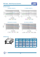
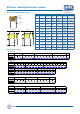


Dimensions
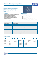
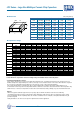
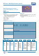
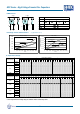
Capacitance Range
TYPE L W T (max) B (min) BW (min)
1515
3.80 0.50
[.15 .020]
3.80 0.50
[.15 .020]
3.20
[.126]
1.60
[.059]
0.30
[.012]
2520
6.35 0.50
[.25 .020]
5.00 0.50
[.20 .020]
3.20
[.126]
4.00
[.157]
0.30
[.012]
3530
8.90 0.50
[.35 .020]
7.60 0.50
[.30 .020]
5.00
[.200]
5.50
[.217]
0.30
[.012]
3640
9.20 0.50
[.36
.020]
10.2
0.50
[.40
.020]
5.00
[.200]
6.00
[.236]
0.30
[.012]
4540
11.5 0.50
[.45 .020]
10.2 0.50
[.40 .020]
5.00
[.200]
7.50
[.295]
0.30
[.012]
5550
14.0 0.50
[.55 .020]
12.7 0.50
[.50 .020]
5.00
[.200]
9.00
[.354]
0.30
[.012]
6560
16.5 0.50
[.65 .020]
15.3 0.50
[.60 .020]
5.00
[.200]
11.50
[.453]
0.30
[.012]
7565
19.0 0.50
[.75 .020]
16.5 0.50
[.65 .020]
5.00
[.200]
14.00
[.551]
0.30
[.012]
Unit : mm [inches]
All values are capacitance EIA codes.
Other dimensions, capacitance values and voltages rating are available. Please contact Holy Stone.
LCC Series - Large Size Multilayer Ceramic Chip Capacitors
Holy Stone
W
T
BW B
L
*Soldering And Handling Precautions:
L
arge ceramic capacitors are more prone to thermal and mechanical cracks. To minimize mechanical cracks, capacitors have to be
handled carefully in the original waffle pack container, carrier tape or other suitable container. Care must be taken that these capacitors
do not come into contact with each other which can cause chip outs, cracks or other mechanical damage.
The recommended method for soldering large chips is reflow soldering. Wave soldering and manual soldering with Iron is not
recommended. Ceramic capacitors must be preheated with less than 2ºC/second rate to about 50ºC below the reflow temperature. Any
sudden increase or decrease in temperature more than the recommended rate, during soldering, may cause internal thermal cracks.
Options:
• HEC offers polymer termination (Super Term) for very large chips to minimize mechanical cracks due to board flexing.
• To minimize the potential for surface arcing in higher voltage applications, HEC offers the option of a proprietary surface coating.
• Pure Tin terminated / RoHS compliant products are offered as a standard, however, lead (Pb) content plated termination may be
provided if required.
• Pd/Ag termination is also offered as an option for Hybrid circuits and other applications.
- 33-
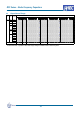
50V
100V
200V
500V
1KV
2KV
3KV
4KV
5KV
8KV
NPO 473 393 363 103 222 821 -- -- -- --
X7R 225 105 474 124 473 682 -- -- -- --
NPO 563 473 393 393 103 222 222 -- -- --
X7R -- -- -- 124 104 103 682 -- -- --
NPO 563 473 393 363 103 392 222 102 471 --
X7R -- -- -- 474 104 103 472 222 182 --
NPO 104 823 563 473 153 472 332 222 561 --
X7R -- -- -- 334 104 103 103 222 222 --
NPO 823 683 563 473 103 392 222 102 471 --
X7R 475 225 474 224 473 153 472 222 102 --
NPO 224 184 104 823 473 103 472 332 102 251
X7R 106 475 225 474 224 473 153 562 222 102
NPO 224 184 104 823 473 123 562 362 122 561
X7R 126 565 225 564 274 683 223 153 103 122
NPO 274 224 124 823 563 223 103 472 152 621
X7R 156 685 225 105 334 104 683 273 223 152
NPO 334 274 154 104 683 333 223 562 182 681
X7R 186 825 275 125 364 124 823 333 273 182
NPO 684 564 474 334 333 273 103 682 332 821
X7R 226 186 106 475 105 334 224 104 473 222
NPO 824 684 564 474 473 333 223 103 472 102
X7R 336 226 186 106 225 364 274 124 563 272
6560
7565
3530
3640
4540
5550
1825
2220
2225
2520
Size Dielectric
Capacitance (pF) maximum
1515