Originalfassung DE BETRIEBSANLEITUNG ABKANTBANK-TAFELSCHERE Übersetzung / Translation EN USER MANUAL SHEAR BRAKE AT 200 Edition: 28.06.
INHALT /INDEX 1 INHALT /INDEX 2 SICHERHEITSZEICHEN / SAFETY SIGNS 4 3 VORWORT (DE) 5 4 TECHNIK 6 4.1 Technische Daten ................................................................................................ 6 5 SICHERHEIT 6 5.1 Bestimmungsmäßige Verwendung ...................................................................... 6 5.2 Unzulässige Verwendung .................................................................................... 6 5.3 Sicherheitshinweise ......................
INHALT /INDEX 13 ERSATZTEILE / SPARE PARTS 13 13.1 Ersatzteilbestellung / spare parts order........................................................ 13 13.2 Explosionszeichnung / explosion drawing .................................................... 14 14 GARANTIEERKLÄRUNG 15 15 GUARANTEE TERMS 16 16 PRODUKTBEOBACHTUNG 17 HOLZMANN MASCHINEN GmbH www.holzmann-maschinen.
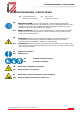
SICHERHEITSZEICHEN / SAFETY SIGNS 2 SICHERHEITSZEICHEN / SAFETY SIGNS DE SICHERHEITSZEICHEN EN BEDEUTUNG DER SYMBOLE SAFETY SIGNS DEFINITION OF SYMBOLS DE ANLEITUNG LESEN! Lesen Sie die Betriebs- und Wartungsanleitung Ihrer Maschine aufmerksam durch und machen Sie sich mit den Bedienelementen der Maschine gut vertraut um die Maschine ordnungsgemäß zu bedienen und so Schäden an Mensch und Maschine vorzubeugen.
VORWORT (DE) 3 VORWORT (DE) Sehr geehrter Kunde! Diese Betriebsanleitung enthält Informationen und wichtige Hinweise zur Inbetriebnahme und Handhabung der ABKANTBANK-TAFELSCHERE AT200. Folgend wird die übliche Handelsbezeichnung des Geräts (siehe Deckblatt) in dieser Betriebsanleitung durch die Bezeichnung "Maschine" ersetzt. Die Betriebsanleitung ist Bestandteil der Maschine und darf nicht entfernt werden.
TECHNIK 4 TECHNIK 4.1 Technische Daten AT 200 Arbeitslänge 200 mm max. Blechstärke 1mm Gewicht 11 kg 5 SICHERHEIT 5.
BETRIEB Arbeitsbereich und Boden rund um die Maschine sauber und frei von Öl, Fett und Materialresten halten! Für eine ausreichende Beleuchtung im Arbeitsbereich der Maschine sorgen! Montieren sie die AT 200 mit den Befestigungslöchern auf eine stabile Werkbank Bei Müdigkeit, Unkonzentriertheit bzw.
WARTUNG Die Vorderseite des Abkantanschlages(2) wie oben abgebildet montieren. WARNUNG Die Biegeeinsätze müssen so montiert werden, dass sie genau in den Abkantanschlag unten beim Biegevorgang eintreten. Biegeeinsätze einsetzen (37-41): Schrauben(5) lösen, Biegeeinsatzwechseln und durch Anziehen der Schrauben wieder fixieren. 6.2 Schneiden Das Blech in die Tafelschere legen und den Handgriff nach oben drücken. Nach Beendigung des Schnittes den Handgriff wieder in Ausgangsposition bringen. 6.
PREFACE (EN) 8 PREFACE (EN) Dear Customer! This manual contains information and important instructions for the installation and correct use of the SHEAR BRAKE AT 200. Following the usual commercial name of the device (see cover) is substituted in this manual with the name "machine". This manual is part of the product and shall not be stored separately from the product. Save it for later reference and if you let other people use the product, add this instruction manual to the product.
TECHNIC 9 TECHNIC 9.1 Technical details AT 200 working length 10 200 mm max. sheet thickness 1mm Weight 11 kg SAFETY 10.1 Intended Use The machine must only be used for its intended purpose! Any other use is deemed to be a case of misuse. To use the machine properly you must also observe and follow all safety regulations, the assembly instructions, operating and maintenance instructions lay down in this manual.
OPERATION Keep your work area dry and tidy! An untidy work area may cause accidents. Avoid slippery floor! Make sure the work area is lighted sufficiently! Mount the Shear Brake by driving the 4 mounting bolts (not included) through the 11/16” mounting holes, into your workbench Always stay focused when working. Reduce distortion sources in your working environment.
MAINTENANCE The rear side of the lower bending die (2) is shown on the back side of the shear brake. Make sure the lower bending die (2) lines up with the upper dies (3, 37-41).The right picture shows the front side of the unit with the lower bending die (2) installed. WARNING Make sure the upper dies you insert are lined up with the lower die Inserting the upper Dies (37-41) Loosen the bolts (5) and insert the desired size die (3, 37-41), or combination of dies and retighten the bolts (5). 11.
ERSATZTEILE / SPARE PARTS 13 ERSATZTEILE / SPARE PARTS 13.1 Ersatzteilbestellung / spare parts order Mit HOLZMANN-Ersatzteilen verwenden Sie Ersatzteile, die ideal aufeinander abgestimmt sind. Die optimale Passgenauigkeit der Teile verkürzen die Einbauzeiten und erhöhen die Lebensdauer.
ERSATZTEILE / SPARE PARTS 13.2 No. 1 Explosionszeichnung / explosion drawing 2 Lower Bending Die 1 No.
GARANTIEERKLÄRUNG 14 GARANTIEERKLÄRUNG (Stand 26.09.2015) Mängelhaftungsansprüche des Käufers aus dem Kaufvertrag gegenüber dem Verkäufer (Holzmann Vertriebspartner) sowie gesetzliche Gewährleistungsrechte des jeweiligen Landes werden durch diese Garantieerklärung nicht berührt.
GUARANTEE TERMS 15 GUARANTEE TERMS (applicable from 26.03.2016) Please consult our troubleshooting section for initial problem solving. Feel free to contact your HOLZMANN reseller or us for Customer Support! Warranty claims based on your sales contract with your HOLZMANN retailer, including your statutory rights, shall not be affected by this guarantee declaration.
PRODUKTBEOBACHTUNG 16 PRODUKTBEOBACHTUNG Wir beobachten unsere Produkte auch nach der Auslieferung. Um einen ständigen Verbesserungsprozess gewährleisten zu können, sind wir von Ihnen und Ihren Eindrücken beim Umgang mit unseren Produkten abhängig: - Probleme, die beim Produktes auftreten Gebrauch des PRODUCT EXPERIENCE FORM We observe the quality of our delivered products in the frame of a Quality Management policy. Your opinion is essential for further product development and product choice.