HOME AUTOMATION, INC. Control & Security System Owner's Manual Document Number 20R00-2 Rev. 2.
Copyright © 2001-2006 Home Automation, Inc.
Contents INTRODUCTION........................................................................................................................................... 1 Underwriter's Laboratories (UL) Listing .........................................................................................................................................1 OVERALL DESCRIPTION .......................................................................................................................... 2 Console Operation ......
CONTROL .................................................................................................................................................... 16 Control Commands ........................................................................................................................................................................16 About UPB...........................................................................................................................................................
Humidity ........................................................................................................................................................................................35 Status..............................................................................................................................................................................................36 Configuring HLC Devices .............................................................................................
PC Access ......................................................................................................................................................................................51 Built-In Ethernet Port.....................................................................................................................................................................52 Controller IP Address, Port Number, and Encryption Key ........................................................................
Set Up Dial ....................................................................................................................................................................................71 Telephone Access .....................................................................................................................................................................71 Answer Outside Call.................................................................................................................
INTRODUCTION Thank you for purchasing your new OmniPro II automation system. You are about to enjoy a new feeling of security, comfort, convenience, and control. OmniPro II coordinates lighting, heating and air, security, scenes, and messages based on your lifestyle and schedule. Please take a few moments to become familiar with all of the features of your system by reviewing this manual. Please keep this manual on file for future reference.
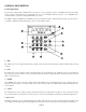
OVERALL DESCRIPTION Console Operation The console is designed with everything that is necessary for you to program and operate your OmniPro II control and security system. Because we feel that it is very important for you to feel comfortable with the operation of your OmniPro II, we recommend that you start by becoming familiar with your console. The OFF (1), DAY (2), NIGHT (3), and AWAY (4) keys are called shortcut keys.
6- UP ARROW The Up Arrow key is used to scroll through menus and lists. The Up Arrow is used to scroll back through a list (for example, if you have already used the down arrow to scroll to an item, the Up Arrow will bring you back to a previous item). 7- CONSOLE LED The Console LED is used to indicate whether the security system is currently armed or disarmed. If armed in any security mode, the LED is set to red. If the system is disarmed, the LED is set to green.
When using the arrow keys to scroll through lists of areas, buttons, codes, temperature zones, units, or zones, only the named items are displayed. If no text description has been given to an item, it will be skipped over when scrolling through that list. You can still enter any item number to access it directly, and then scroll up and down among the named items. To look at another specific item, simply enter the item number followed by the Down Arrow key.
Confirmation Beep When you have successfully completed a function, such as entering a program or changing a setup item, the console will beep once. Cancel If you are ever unsure and wish to return to the top-level display, press the ' * ' key. You may have to press it more than once, depending on how far into the function (menu) you are. Each time you cancel out of an operation, the console will beep once to indicate that you have canceled.
SECURITY SYSTEM OPERATION Disarming the Security System and Silencing Alarms Before going any further, you should know how to disarm your security system in the event that the alarm sounds. Turning the system OFF disarms the burglar alarm, resets the fire and emergency alarms, and silences all sirens and sounders. Press the OFF key. OFF Now enter your four digit Code. 1 1 1 1 That's all there is to it. Watch the display.
2 = NIGHT The NIGHT mode is used when you are asleep and everyone in your household is at home. In the Night mode, your doors, windows, and non-sleeping area (i.e. downstairs) motion detectors are armed. In the Night mode, there is no entry delay. The alarm system sounder will be activated immediately if any door, window, or non-sleeping area (motion detector) is tripped. 3 = AWAY Use the AWAY mode when you leave your house and no one is home. All doors, windows, and motion detectors are armed.
Quick Arm For extra convenience, the OmniPro II can be armed by simply pressing the DAY, NIGHT, or AWAY button twice, eliminating the need to enter the code. To quick arm the system in the Away mode, from the top-level display, press AWAY AWAY . The quick arm feature only works if the alarm system is in the Off mode, and if no alarms are sounding. This feature is disabled when the system is shipped. If desired, it can be enabled or disabled at any time - See Set Up Arming, Enable Quick Arm.
#=GOTO To Bypass or Restore a zone in another area, you must first "go to" that area by selecting #=GOTO. AREA: ENTER AREA: At this point you may enter the area number followed by the ' # ' key, or use the down arrow key to scroll to the next area - See Area Arming for additional information.
For more information on the digital and voice dialer - See Digital Dialer and Voice Dialer. • The system continues to sound all alarms and flash the flashing light for 1-30 minutes after the alarm is activated. • After a 1-30 minute period, the sounder is turned off, and the alarm system resets itself. The console beeper stays on. If a zone is tripped after a reset, the sounder will again be activated, and the dialer will again dial out. At any time, the alarm system can be turned off at the console.
Police Emergency When the 1 key and the 3 keys are pressed simultaneously, the Police Emergency alarm is activated. This alarm operates exactly the same as described for Burglar Alarm Activated except: • The console display indicates: "BURGLARY! - POLICE EMERG TRIPPED". • The interior sounder and the outdoor siren are activated immediately. There is no outside siren delay. Fire Emergency When the 4 key and the 6 key is pressed simultaneously, the Fire Emergency alarm is activated.
Trouble Indications The OmniPro II constantly monitors the alarm zones and several internal matters and will alert you if it detects trouble. The particular trouble is indicated on the bottom line of the display and a trouble signal is given by beeping the console beeper continuously, 2 beeps per second. When any trouble condition occurs, the console will beep twice per second and continue to beep until the ' * ' key (cancel) is pressed to acknowledge the trouble.
Manager Code The Manager codes can arm/disarm the security system in assigned areas, during assigned times. The Manager code can access functions that are code protected in High Security mode. Managers may also access the system from an outside telephone line. User Code User codes can only be used to arm and disarm the security system in assigned areas when the time assigned to that code is valid.
If the ' 0 ' (ALL) key had been selected, the display will show: DISARM ALL AREAS ENTER CODE: #=AREA As the four-digit code is entered, "X" characters are echoed after the "ENTER CODE:" prompt. If the Master code or a valid code is entered, the console will beep one time and Area 2 will be disarmed. Even if Auto Bypass is enabled, the system will not arm another area if any zones in that area are not ready.
Testing Your System HAI recommends testing your system on a weekly basis to ensure that you are fully protected. 1. Notify your Central Station that you intend to test the system. To test the siren, press the 1 and 3 keys simultaneously. Press OFF and enter your Code to cancel the alarm and silence the siren. 2. To test the security zones, you will need a partner to walk around your home and open and close all doors, windows, etc. that are connected to the system while you watch the console.
CONTROL Control Commands The control features of the OmniPro II make it easy and convenient to control almost any light or appliance from the console or over the telephone. You may also have your heating and air conditioning (HVAC) under control of the system, which will allow you to save energy dollars by setting the temperature appropriately when you are home, asleep, or away. Furthermore, the OmniPro II can be used to program lights to make the home or business look occupied as a deterrent to thieves.
When set to UPB, the OmniPro II controller can: ¾ ¾ ¾ ¾ ¾ ¾ ¾ ¾ Send commands (on, off, bright, dim and level) to individual switches and modules Receive commands and status from individual switches and modules Send commands to keypad controllers to change scenes and control LED backlight behind the keys Receive commands when buttons are pressed on keypad controllers to activate controller macros Send Link commands to switches, modules, and keypad controllers to activate scenes Receive Link commands when a
When “Status Tracking” is enabled (this is the default setting), OmniPro II keeps track of the exact status of each unit even when a lighting scene is initiated by the Room Controller. Room Controllers also keep track of when individual switches in a room are turned on and off. When all of the lighting loads in a room are turned off, the “Off” indicator is illuminated.
A Zone is any individual RadioRA Switch or Dimmer. A RadioRA System has a maximum of 32 Lighting Zones. Zone Numbers can be used to identify any individual Zone (one Switch or one Dimmer), in a RadioRA system via the RS232 Interface. The Chronos System Bridge and Timeclock bridges two RadioRA systems for a total of 64 Lighting Zone Controls and 24 Master Controls.
Unit Numbers OmniPro II systems have 511 total Unit Numbers.
Scrolling Through Names The OmniPro II stores names for Units, Zones, Buttons, Codes, Temperatures, and Messages so that you don't have to remember that "UNIT 5" is the "DEN LIGHT" and "ZONE 1" is the "FRONT DOOR". In general, any time you enter a unit, zone, button, code, temperature, or message number, you can press the down arrow key to display its name, then use the up and down arrow keys to scroll through the list of other names. This is true when entering commands and programming on the console.
Each lighting scene can also be set or easily changed using the pushbuttons on the HAI UPB™ 6-Button Room Controller, as follows: Step 1 2 3 4 Operation Press the desired pushbutton on the HAI UPB™ 6-Button Room Controller to activate the current scene (preset lighting level) in each of the HLC devices. Use the local Decora-style rocker switch on each UPB™ Wall Switch Dimmer(s) to set the desired lighting level(s) or issue commands from the OmniPro II controller.
¾ Press 4 (LVL) to set the desired lighting level of the selected unit (0%-100%). ¾ 5 (RMP) does not affect CentraLite units. ¾ Press 9 (TIM) to time the selected unit (On or Off). Timed commands may be from 1-99 seconds, 1-99 minutes or 1-18 hours. ¾ Press # (STA) to see the status (On or Off) of a CentraLite device.
Ramp Command (ALC) When ALC Switch Modules are being used, it is possible to ramp the lighting level of an ALC Dimmer Switch to a new level at a selectable ramp rate. Only ALC Dimmer Switches respond to the Ramp command. Press the 5 (RAMP) key to select the ramp command. The keypad will then prompt you for the desired ramp rate: ENTER RATE: MINUTES (1-99) #=H/M/S The rate specifies the time it takes the switch to go from full off to full on, or from full on to full off.
Timed Commands The timed commands allow a units to be turned on or off for a specified period of time. The unit may be turned On for 1-99 (minutes or seconds), or 1-18 hours, then Off; or turned Off for 1-99 (minutes or seconds) or 1-18 hours, then On. Lighting units (1-256) may also be dimmed or brightened for a specified period of time.
Controlling Outputs The OmniPro II has eight outputs that can be used to switch relays. Outputs 1-8 are controlled as Unit Numbers 385-392, respectively. If the Interior Horn is configured as a "General Purpose" output, Unit Number 393 is used to control the output. If the Exterior Horn is configured as a "General Purpose" output, Unit Number 394 is used to control the output. In this configuration, Unit Numbers 393 and 394 should not be used as "Flags".
NOTE: The All Off function can be changed, if desired - See Set Up Misc, All On And All Off. Leviton Scene Control OmniPro II supports Leviton Scene Control (a feature found in certain Leviton Switches). There are 256 Scenes that can be set and executed. The Leviton Switches are divided into "lighting groups" of four units each. Each of these lighting groups can be set to four different Scenes.
Scene Off Command Once the Scenes have been sent, press the 0 (OFF) key to command the four units in that Scene to turn off. Notes: 1. When sending Scene Commands, the controller must be configured to allow Extended Code transmissions on each House Code affected by a Scene. 2. The Scene Commands always apply to a group of four consecutive units, which are units 1-4, 5-8, 9-12, and 13-16 on a particular house code.
Executing Phantom Buttons OmniPro II can turn on and turn off each of the 17 possible Phantom Buttons. Phantom Buttons must be pre-programmed into the RS-232 interface or Chronos. Phantom Button 16 is always assigned to “All On” (if the Phantom button is turned on or off) and Phantom Button 17 is always assigned to “All Off” (if the Phantom button is turned on or off).
Buttons A powerful feature of the OmniPro II is the ability to program Buttons. A Button (also known as macro) is a number on the keypad that is programmed to execute a series of commands when it is pressed. Buttons are used to program functions that are specific to your home and lifestyle. Using a button, you can activate several commands at once. You can personalize 128 buttons with descriptive names.
HAI RC-Series Thermostats The following control actions are allowed for HAI Communicating Thermostats: • • • • • Set heating setpoints Set cooling setpoints Set system mode (Off / Heat / Cool / Auto) Set fan (On / Auto) Turn hold On and Off NOTE: Not all actions are applicable to every type of thermostat. To enter the temperature menu, from the top-level display or from the main menu, press the 5 (TEMP) key on the console keypad. You will be prompted with the first named temperature zone (i.e. Upstairs).
The fan control on a thermostat may be switched between on and auto by selecting 4 (FAN) from the temperature menu: Upstairs FAN 0=AUTO 1=ON Thermostats may be switched between hold mode and the normal run mode. While in hold mode, the thermostat does not respond to scheduled temperature changes but instead maintains the temperature at its current setting. The thermostat will then return to its scheduled operation setting once hold mode is removed.
The following control actions are allowed on PESMs: • • • • Turn Energy Saver On and Off Turn Energy Saver On and Off for a specified time Set heating setpoint Set cooling setpoint You can turn the energy saver on, off, use a timed on/off, and change the Heat and Cool temperatures from the console or by telephone. Commands can also be programmed so that they occur by time schedule or by event, such as security mode change.
Downstairs 0=OFF 1=ON 2=HEAT ↓ Downstairs 3=COOL 9=TIME #=STAT ↑ ENTER TIME MINUTES (1-99) #=H/M/S Downstairs 0=OFF 1=ON FOR 15M ↓ The current status of a temperature zone may be displayed by selecting ' # ' (STAT) key from the main temperature menu. The status display differs depending on the temperature zone type. When you are finished, press the ' * ' key twice to return to the top-level display.
Upstairs 2=LOW 3=HIGH #=STAT For negative temperatures (-1o to -40o), press the ' # ' key prior to entering the temperature to make the number negative. A Celsius temperature may also be specified in 0.5 degree steps if three numeric digits are entered. The third digit adds a .5 to the first two digits if it is any- thing other than zero. Enter a leading zero if necessary.
Status The Status function is used to display the status of various items in the system. To enter the status menu, from the top-level display or the main menu, press the 6 (STATUS) key on the console keypad. STATUS 1=CTRL 4=TEST 2=ZONE 3=SUN ↓ 5=TEMP 6=ENERGY ↑ 1 = CTRL (CONTROL UNITS) The Control Status menu allows you to view and scroll through the status of each control unit and to configure HLC and UPB devices.
Press 1 (CTRL) to view the current status of each unit and to configure the HLC device that is assigned for each unit. The console will display: Porch Light STATUS OFF ↓ You may enter a unit number to display the selected unit, or simply press the down arrow key to scroll through the list of named units. When the desired unit is displayed, put the selected HLC device into Setup Mode (See - Setup Mode for HLC Devices), and then press the ' # ' key twice (i.e. # #).
2 = ZONE The Zone Status menu allows you to view and scroll through the status of each zone input. To enter the Zone menu, from the Status menu, press the 2 (ZONE) key on the console keypad. The system will display: Front Door ZONE 1 SECURE ↓ You may enter a zone number to start displaying the status with zone, or simply press the down arrow key to start with the first zone. The arrow keys may be used to continue scrolling between zones.
The next series of displays shows the current analog reading for each security zone input. The displays show the readings for zones 1-176. 1=147 4=146 2=148 5=146 3=147 6=147 THROUGH 175=148 176=147 ↑ Normal readings for zones are between 137 - 157 when secure. If Zones 1-4 are configured as Fire or Gas zone, normal readings are between 26 - 43 when secure. Each reading should be changing only by two or three counts from its average steady reading.
Event Log The Event Log records the 250 most recent significant security system Events (happenings) and trouble conditions in the system. When a new event occurs, the oldest one is lost. The following Events, along with the time and date of their occurrence are recorded in the Event Log when they occur: • • • • • • • All Security system Armings and disarmings (Off, Day, Night, Away, and Vacation), and user name. All zones bypassed or restored by the user, and user name.
Messages The Message menu is used to play and record the memo message and to quickly clear all text messages. The memo message is an eight-second voice message. It's like an "electronic notepad" for a family member to leave a handy message. After a message is recorded, it can automatically be played back when someone returns and disarms the security system. The Message menu is also used to show, log, clear, and send text messages, and to say and phone (dial out) your voice messages.
Show Message The 1 (SHOW) key allows you to display the selected text message(s) on the console's top-level display. This can be a helpful reminder of special events and occasions. TRASH NIGHT ENTER MESSAGE ↓ You may enter the message number followed by the ' # ' key to display that message, or simply press the down arrow key to scroll through a list of messages.
Send Message (Pro-Link) The 6 (SEND) key allows you to send any of the text messages through the Pro-Link serial port. You are first prompted to specify the desired serial port. SERIAL PORT: 1-4 The built-in serial ports (J1-J3) on the controller are assigned to Serial Port 1 - Serial Port 3, respectively. Serial port 4 is a Serial Interface Module connected to the Expansion port on the controller. Next, select the message to be sent.
TELEPHONE CONTROL Telephone Interface Your OmniPro II is equipped with a built-in telephone response feature that allows you to control and access the status of your system from any Touch-Tone phone. The OmniPro II actually talks to you using a digital recording of an actual human voice, so the sound is incredibly life like. You send commands to the OmniPro II using the keys of your Touch-Tone telephone.
Phone Access Denied - Remote Lockout The OmniPro II has a remote lockout feature to discourage youngsters (and adults who act that way) from trying to access your system. If four invalid codes are entered, the system will hang up and a one-hour lockout period will begin. During the lockout period, the OmniPro II will not answer a call after any number of rings, which should discourage the caller.
1 - Control Press 1 from the MAIN MENU to get to the CONTROL menu. If voice descriptions have been programmed, after a three-second delay, the system will begin reading from the list of units (OmniPro II will say the unit number then its description). The OmniPro II will read three units, then say, "PRESS POUND TO CONTINUE." If the ' # ' key is pressed, OmniPro II will read the next three unit numbers and descriptions (if programmed). 2 - Security Press 2 from the MAIN MENU to get to the SECURITY menu.
Press the temperature zone you wish to control, then press #. Press the ' 0 ' key to select all HAI Thermostats. This is a simple way to broadcast the new Heat or Cool setting or change the system mode, fan mode, or hold mode of all HAI thermostats in your system. When an HAI Communicating Thermostat is entered: "THERMOSTAT 1 - THERMOSTAT 1 - TEMPERATURE IS (TEMP).
8 - Message This command allows you to record and verify the voice memo message, allows you to record and play custom messages (phrases), and allows you to record and verify your address. If an optional HAI Two-Way Audio Module is being used, this command also allows paging and listening to the premises. Press 8 from the MAIN MENU to get to the MESSAGE menu. "MESSAGE - PLEASE CHOOSE: 1 PLAY MESSAGE, 2 RECORD MESSAGE, 3 INTERIOR, 6 PLAY PHRASE, 7 RECORD PHRASE, 8 PLAY ADDRESS, 9 RECORD ADDRESS, *: CANCEL.
To play one of the custom phrases, press the 6 key. " PLAY PHRASE: ENTER PHRASE NUMBER, THEN POUND." Press the phrase number (1-60) you wish to play, then press #. "PHRASE IS: (OMNIPRO II PLAYS PHRASE)." To record one of the custom phrases, press the 7 key. " RECORD PHRASE: ENTER PHRASE NUMBER, THEN POUND." Press the phrase number (1-60) you wish to record, then press #. "RECORD PHRASE - [BEEP]" At the [BEEP], record your custom phrase… At the second [BEEP]: "PHRASE IS: (OMNIPRO II PLAYS PHRASE).
Emergency Dial-Out Emergency dial out consists of two distinct parts: the "digital dialer" and the "voice dialer." Digital Dialer The digital dialer (also called a "digital communicator") reports alarm events to a central station monitoring center. The digital dialer sends a digitally coded message to the central station's receiver and computer. The computer in the central station presents your name, address, and other information to a human operator who notifies the appropriate authorities.
After it has dialed the last number in the dial order, the OmniPro II stops dialing and reconnects the in-house phones. What You Hear - If Your OmniPro II Calls You When you pick up the phone and say something, the OmniPro II will say one of the following, depending on type of alarm: - BURGLAR ALARM FIRE ALARM AUXILIARY ALARM TEMPERATURE ALARM WATER ALARM GAS ALARM SILENT ALARM AND - ADDRESS: (Your address here) PHONE NUMBER (your phone number here) The OmniPro II will repeat this message twice.
Built-In Ethernet Port The built-in Ethernet port (J6) allows a device to connect to the OmniPro II controller via a network (i.e. Ethernet, Internet) using a secure, encrypted communication link. The Ethernet port transports HAI application-level packets containing Omni-Link serial protocol messages over IP. The controller supports 3 unique client “sessions” which means 3 devices may actively be connected and communicating with the controller simultaneously over the Ethernet port.
192.168.0.101 HAI OmniPro II Controller To connect to an OmniPro II controller on a local network using HAI PC Access, under Configure >> Network enter the controller’s IP address: Hub or Router 192.168.0.50 Computer (i.e. 192.168.0.101) 192.168.0.
To connect to an OmniPro II controller from the Internet using HAI PC Access, under Configure >> Network enter the public IP address: To connect to an OmniPro II controller on a local network using HAI PC Access, under Configure >> Network enter the controller’s IP address: (i.e. 134.42.112.8) (i.e. 10.0.0.
SETUP Configuration and Advanced Control Programming (ACP) The Setup menu is used to configure operating parameters, program your system to do its automated control and security functions using ACP, and give text and voice descriptions to all of your zones, units, buttons, codes, temperatures, and messages. To enter the Setup menu, from the top-level display or from the main menu, press the 8 (SETUP) key on the console keypad.
The display will show all areas that have been enabled for that user. After the area(s) is/are selected, press the ' # ' key. CODE 2 AREAS: 1 2 0=CLR You can specify the access (on/off) times for the code; this is, the time periods during which the code is valid. CODE 2 ON TIME: 8:00 AM MTWTF-- #=CHNG CODE 2 OFF TIME 5:00 PM MTWTF-- #=CHNG The times and days are changed by pressing the ' # ' key. Choose the 1 (TIME) key to change the On or Off times. You will be prompted to enter the new time.
Advanced Control Programming (ACP) Your OmniPro II can be programmed to do automated control and security functions on a time schedule or in response to an event occurring in the system.
Menu 1 Menu 2 Menu 3 Menu 4 Menu 5 Menu # - Programs for a particular control unit number All Security related programs Programs for a particular macro button Programs for All On/Off functions Programs for a particular Temperature zone Displays every program Selecting the 1 (CTRL) or 5 (TEMP) key will prompt you to specify the desired unit or temperature zone. These can be specified by entering the number, followed by the ' # ' key or by using the arrow keys to scroll through a list of items.
The arrow keys are used to scroll through the programs. Pressing the ' # ' key while a particular program is displayed will allow that program to be edited or deleted. The display shows: SHOW PROGRAM 1=EDIT 2=DELETE ¾ Press the 1 (EDIT) key to edit the selected program. The Edit Program menu is displayed which allows the various parts of the program to be changed - See Edit Program. Edit each part of the program as specified under Edit Program.
Edit Programs When Selecting the 1 (WHEN) key, from the Edit Program menu, allows the time or button/event that activates the program to be changed. The display shows: EDIT WHEN 1=TIMED 2=BUTTON Times Programs Selecting 1 (TIMED) sets the program to be activated at a specific time of day. You are prompted to enter the time and date or days of week. The current default value is shown for each item. Press ' # ' to accept the default. 12:00 AM 5/17 1=TIME 2=DATE/DAY Select 1 (TIME) to enter the new time.
Button and Event Programs Selecting 2 (BUTTON), from the "Edit When" menu, sets up a program to be activated when a macro button is executed or an event occurs. The user is prompted to specify the button/event that activates the program: BUTTON: ENTER BUTTON #=MENU ↓ A specific macro button may be activated by entering the button number followed by the ' # ' key, or by using the arrow keys to scroll through a list of buttons. To program specific event buttons (i.e.
Corresponding Switch Table Switch 1 2 3 4 5 6 7 8 9 10 OmniPro II 2 3 4 5 6 7 8 9 10 11 UPB 6-Button Keypad On Button Off Button A B C D UPB 8-Button Keypad 1 or E 2 or F 3 or G 4 or H 5 or I 6 or J 7 or K 8 or L RadioRA Master Control 1 2 3 4 5 6 7 8 9 10 ALC 4-Button 1 2 3 4 Security Mode Event Buttons Pressing the 2 (SEC) key allows you to select the event button that will be activated when a security mode changes: 0=OFF 3=AWAY 1=DAY 2=NIGHT 4=VACATION After the security mode is selected, an addi
AREA: ENTER AREA 0=ALL ↓ The area number should be entered followed by the ' # ' key, or the arrow keys may be used to scroll through a list of areas. WHEN C1 A1 AWAY: 1=DELAY 2=CODE 3=AREA Zone Event Buttons Pressing the 3 (ZONE) key allows you to select the event button for a zone activation event. You are first prompted to enter the desired zone number: ZONE: ENTER ZONE ↓ The zone number should be entered followed by the ' # ' key, or the arrow keys may be used to scroll through a list of zones.
Alarm Event Buttons Pressing the 5 (ALARM) key allows you to specify an event button activated upon the occurrence of an alarm. You are first prompted to select the type of alarm: SELECT ALARM TYPE ANY TYPE ↓ The arrow keys are used to select from a list of alarm types: • • • • • • • • • ANY ALARM BURGLARY ALARM FIRE ALARM GAS ALARM AUXILIARY ALARM FREEZE ALARM WATER ALARM DURESS ALARM TEMPERATURE ALARM Press the ' # ' key when the desired alarm type is shown.
The arrow keys are used to select from a list of event buttons: • • • • • • • • • • • • • • • WHEN WHEN WHEN WHEN WHEN WHEN WHEN WHEN WHEN WHEN WHEN WHEN WHEN WHEN WHEN ENERGY LO ENERGY MID ENERGY HI ENERGY CRIT PHONE DEAD PHONE RING PHONE OFFHK PHONE ONHOOK AC PWR OFF AC PWR ON BATTERY LOW BATTERY OK DCM FAIL DCM OK CAMERA* (PA Access only) *When a camera input (1-6) is pressed on an OmniTouch with Video. This item can only be programmed via PC Access.
Edit Program Command Selecting 2 (CMD), from the Edit Program menu, allows the commanded action for the program to be specified. The following menu is displayed: 1=CONTROL 3=BUTTON 2=SECURITY 4=ALL ↓ 5=TEMP 8=MESSAGE 6=ENERGY ↑ After the command is specified, the display returns to the Edit Program menu: Program Control Commands Press the 1 (CONTROL) key to command lights and appliances. Specify the desired command - See Control.
Unit Toggle Command Using HAI PC Access Software, you can create programs to toggle any unit (1-511) from its current state to the opposite state. When the program is executed, the unit will toggle to Off if the unit is currently in a non-off state (On, On for time, Level 1-100, Scene A-L, Dimmed Steps, Dimmed for time, Brightened Steps, or Brightened for time). When the program is executed, the unit will toggle to On if the unit is currently Off.
Program Video Commands* This program command is used to display video automatically on an OmniTouch with Video touchscreen when an event occurs. You can specify which camera and which touchscreen(s) will display the video when the event takes place. When the event takes place, it switches each of the specified touchscreens to full screen video. * This item can only be programmed via PC Access.
Edit Program Condition Selecting the 3 (&COND) key, from the Edit Program menu, allows the condition for the program to be specified. The condition is optional in all program lines. This condition must be true when the program time or event occurs for the program to executed. Note: Two (2) conditions can be specified in each program line; however, when programming from the console, only 1 condition can be selected.
The zone will be displayed and you will be prompted for the state of the zone: IF Front Door: 0=SECURE 1=NOT RDY Program Time Clock Conditions Select the 9 (TIME) key to specify that the program should only execute if a specified Time Clock is either On or Off. The display prompts you for the Time Clock number: ENTER TIME CLOCK: 1-3 Enter the Time Clock number followed by the ' # ' key.
Set Up Dial The Set Up Dial menu is used to configure all of the telephone related items for the OmniPro II. To enter the Set Up Dial menu, from the Setup menu, press the 4 (DIAL) key. Use the arrows to scroll through the items. For each item, the top line displays a description of the item and its current setting. The bottom line shows the available ranges for your selections. Phone numbers can be up to 24 characters long. The number is shown on the bottom line of the display.
Dial Out Number 1 Dial Out Number 1 is one of the 8 numbers that are stored in the system. In the event of an alarm, these numbers are dialed in the order that is set up in the Dial Out Order for the particular type of alarm. Dial out numbers 1 - 8 have On and Off times and days, so that no time is wasted calling you at the office at night or on a Sunday if the alarm is activated. For dial out number 1, you should enter your office number where you can be reached during working hours.
Set Up Arming To configure different arming and disarming options, from the Setup menu, press the 5 (ARM) key. Entry Delay The Entry Delay is the time, in seconds, that you have to turn off the alarm after entering your home. The Entry Delay only applies to the entry/exit zone (i.e. your doors). If you (or someone else) come in through a window, there will be no entry delay and the alarm will sound immediately. When you come in through a door on an entry/exit zone, the other zones are delayed too.
Enable Quick Arm The Quick Arm feature allows the security system to be armed by pressing the desired mode key twice instead of having to enter your code. The default setting for Enable Quick Arm is No. Enable Auto Bypass The Auto-Bypass feature allows the system to automatically bypass an open zone when the system is armed, rather than setting off the alarm. In some applications, it may be preferable to allow arming only if all zones are secure (READY).
Enable Freeze Alarm If there are one or more Thermostat or PESM in a system, they can also be used to detect a freeze condition - See Freeze Alarm. The default for Enabled Freeze Alarm is No. Flash For Alarm You may enter one unit number that will flash on and off continuously when the alarm is activated. This should be an outside light to alert neighbors and police to your property if the alarm is activated. The default Flash For Alarm is Unit 2.
House Codes 1-16 All On This feature allows you to choose if House Code 1-16 will respond to the “All On” command. Press the 0 key to select No and the 1 key to select Yes. After selecting, press the down-arrow key to change this option for the next House Code. HC 1 ALL ON: 0=NO 1=YES 1 The default setting for HC 1-4 All On is Yes. Notes: 1. When configured, each House Code will affect 2 rooms of HLC lighting (i.e. HC 1 ALL ON affects Room 1 and 2). 2.
Latitude, Longitude, and Time Zone The system automatically calculates the time of sunrise and sunset each day. Sunrise/sunset can be specified as the time a scheduling command is executed, as an enable/disable time, or as a darkness condition on a scheduling command or event button. To enable the system to properly calculate sunrise and sunset times, you must enter your latitude, location north or south of the equator, longitude, location east or west of the Prime Meridian, and time zone.
DST START WEEKEND: FIRST SUNDAY #=CHNG DST END MONTH: 1-12 0=DISABLE 10 DST END WEEKEND: LAST SUNDAY #=CHNG ↑ Set the value for DST Start and End Months to "0" if Daylight Savings Time does not apply to your region, or to disable this automatic time update feature. The DST Start and End Weekend takes place on the specified Sunday (1-7) at 2:00 AM. To change the DST Start or End Weekend, press the ' # ' key, then use the arrow keys to scroll through the list. Press the ' # ' key to make the new selection.
Encryption Key Encryption and decryption of data between the OmniPro II controller and the connected device is based on the Advanced Encryption Standard (AES) using a 128-bit cryptographic key. A unique encryption key is randomly assigned to each OmniPro II controller at the factory (no records of these keys are kept at the factory). It may be left the same (recommended) or it may be changed as desired.
Set Up Voice The OmniPro II can be set up to speak descriptive names such as "FRONT DOOR" for control zones, units, buttons, codes, temperatures, areas, and messages. These names will be spoken over the telephone along with the item number that is normally spoken. Voice descriptions for messages can be spoken over a speaker when used with a Two-Way Audio Module. To enter the Set Up Voice menu, from the Setup menu, press the 8 (VOICE) key.
UNDERWRITER'S LABORATORIES REQUIREMENTS For a complete list of requirements and restrictions when installing the OmniPro II panel in a UL Listed system, refer to the Underwriter's Laboratories Requirements section of the Installation Manual (10I00-2). When used in UL Listed Installations, the following items apply: 1. The "High Security Mode" must be ON. 2. The "Enable Auto Bypass" feature must be OFF. 3.
FEDERAL COMMUNICATION COMMISSION NOTICE: 1. This equipment complies with Part 68 of FCC Rules. On the door, inside of the OmniPro II enclosure, is a label that contains, among other information, the FCC registration number and Ringer Equivalence Number (REN) for this equipment. If requested, provide this information to your telephone company. 2. An FCC compliant telephone cord and modular plug is provided with this equipment.
CANADIAN INDUSTRY CANADA NOTICE Notice: The Industry Canada label identifies certified equipment. This certification means that the equipment meets certain telecommunications network protective, operational and safety requirements. The Industry Canada does not guarantee the equipment will operate to the user's satisfaction. Before installing this equipment, users should ensure that it is permissible to be connected to the facilities of the local telecommunications company.
APPENDIX A - DIAL OUT PLANNER Use the following dial-out planner to help you set-up the voice dial-out numbers: OmniPro II Voice Dial-Out Planner DIAL OUT NUMBER 1: __________________________________ AREA: _____________ DIAL OUT 1 ON: TIME: _______________ DAYS: _______________ DIAL OUT 1 OFF: TIME: _______________ DAYS: _______________ DIAL OUT NUMBER 2: __________________________________ AREA: _____________ DIAL OUT 2 ON: TIME: _______________ DAYS: _______________ DIAL OUT 2 OFF: TIME: __________
INSTRUCTIONS TO CALLED PARTY Dear ___________________________________________________________________ I have programmed my OmniPro II Home Automation system to call you if my alarm is activated. If it is activated, it will call and say: "Emergency... Emergency...
APPENDIX B - TEXT DESCRIPTION CHARACTER CODES CODE CHAR CODE CHAR CODE CHAR CODE CHAR 00 SPACE 24 8 48 P 72 h 01 ! 25 9 49 Q 73 i 02 " 26 : 50 R 74 j 03 # 27 ; 51 S 75 k 04 $ 28 < 52 T 76 l 05 % 29 = 53 U 77 m 06 & 30 > 54 V 78 n 07 ' 31 ? 55 W 79 o 08 ( 32 @ 56 X 80 p 09 ) 33 A 57 Y 81 q 10 * 34 B 58 Z 82 r 11 + 35 C 59 [ 83 s 12 , 36 D 60 ¥ 84 t 13 - 37 E 61 ] 85 u 14 .
APPENDIX C - VOICE DESCRIPTION CODES CODE 255 58 254 29 30 26 256 31 32 257 33 258 259 34 260 35 198 261 262 263 264 195 36 265 266 37 267 199 268 269 270 271 38 272 273 39 274 275 40 276 41 277 42 278 279 280 43 44 45 281 46 282 283 284 285 DESCRIPTION (ADDRESS MSG) (BEEP) (MEMO MESSAGE) (PAUSE) (SHORT PAUSE) A. M.
CODE 341 80 81 342 343 344 217 5 17 218 345 82 219 16 346 347 220 221 348 15 349 350 14 4 83 84 351 352 353 85 354 355 222 86 223 356 87 357 88 224 89 90 358 92 359 91 360 361 362 363 364 93 94 365 95 96 366 367 368 97 DESCRIPTION FALL FAMILY FAN FATHER’S FAULT FEBRUARY FENCE FIFTEEN FIFTY FILE FILTER FIRE FIRST FIVE FLAG FLOOD FLOOR FLOW FORCE FORTY FOUNDATION FOUNTAIN FOUR FOURTEEN FOYER FREEZE FREEZER FRIDAY FROM FRONT FULL FUNCTION FURNACE FUSE GALLERY GAME GARAGE GARDEN GAS GATE GIRL'S GLASS GO GO TO
CODE 444 445 233 446 131 447 448 132 133 449 450 234 235 27 134 451 452 453 454 135 455 136 137 456 457 138 458 459 460 461 139 140 462 141 142 143 144 463 464 145 465 146 466 467 468 147 469 470 471 472 148 236 149 473 474 150 151 475 152 476 DESCRIPTION ONLINE ONLY OPEN OPTION OR OTHER OUT OUTDOOR OUTLET OUTSIDE OVER OVERFLOW OVERHEAD P. M.
CODE 250 536 537 538 539 540 541 542 251 543 187 544 28 545 188 189 546 252 547 548 549 253 550 190 601 602 603 604 DESCRIPTION VAULT VCR VIDEO VISITOR VOLUME WAITING WALK WALKWAY WAREHOUSE WARNING WATER WEDNESDAY WELCOME TO OMNI WELCOME WEST WINDOW WINE WING WINTER WOOD WORK YARD YOU ZONE PHRASE 1 PHRASE 2 PHRASE 3 PHRASE 4 CODE 605 606 607 608 609 610 611 612 613 614 615 616 617 618 619 620 621 622 623 624 625 626 627 628 629 630 631 632 DESCRIPTION PHRASE 5 PHRASE 6 PHRASE 7 PHRASE 8 PHRASE 9 PHRASE 1
NOTE TO INSTALLER Following installation, this manual shall be left for the homeowner's use.