Item #1002 543 114, 1002 543 113, 1002 543 115, 1002 543 116 Model #91662, 91663, 91661, 91666 UL Model #52-WWDIV USE AND CARE GUIDE WINDWARD IV 52-INCH CEILING FAN Questions, problems, missing parts? Before returning to the store, call Home Decorators Collection Customer Service 8 a.m. - 6 p.m., EST, Monday-Friday. 1-800-986-3460 HOMEDEPOT.COM/HOMEDECORATORS To view an instructional video on how to install this product: 1. Go to www.homedepot.
Table of Contents Table of Contents................................................................. 2 Assembly............................................................................... 7 Safety Information................................................................ 2 Operation............................................................................ 14 Warranty................................................................................ 3 Care and Cleaning................................
Warranty The supplier warrants the fan motor to be free from defects in workmanship and material present at time of shipment from the factory for a lifetime after the date of purchase by the original purchaser. The supplier also warrants that all other fan parts, excluding any glass or acrylic blades, to be free from defects in workmanship and material at the time of shipment from the factory for a period of two years after the date of purchase by the original purchaser.
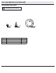
Pre-Installation (continued) HARDWARE INCLUDED NOTE: Hardware not shown to actual size.
Pre-Installation (continued) PACKAGE CONTENTS A H B I J C D K ON E L F M G Part Description Quantity A Slide-on mounting bracket (inside canopy) 1 B Ball/downrod assembly C Part Description Quantity H Blade 5 I Glass bowl 1 1 J LED bulbs (9.5 Watt, max.
Installation MOUNTING OPTIONS NOTE: You may need a longer downrod to maintain proper blade clearance when installing on a steep, sloped ceiling. The maximum angle allowable is 30° away from horizontal. WARNING: To reduce the risk of fire, electric shock or personal injury, mount to outlet box marked “acceptable for fan support of 35lbs. (15.9 Kg) or less” using the screws provided with the outlet box.
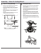
Assembly - Standard Ceiling Mount 1 2 Preparing for mounting □□ Remove the canopy ring (FF) from the canopy (C) by turning □□ □□ □□ Route the wires exiting the top of the fan motor assembly (E) into the decorative motor collar cover (D) and through the canopy ring (FF). the ring counter-clockwise until it unlocks. Remove the mounting bracket (A) from the canopy (C) by loosening the two canopy screws (JJ) located in the “L shaped” slots. Remove and save the two canopy screws (II) in the round holes.
Assembly - Close-To-Ceiling Mount 1 2 Close-to-Ceiling Mounting □□ Remove the canopy ring (FF) from the canopy (C) by turn□□ □□ □□ JJ Routing the wires □□ Remove three of the six screws and lock washers (KK)(every ing the ring counter-clockwise until it unlocks. Remove the mounting bracket (A) from the canopy (C) by loosening the two canopy screws (JJ) located in the “L shaped” slots. Remove and save the two canopy screws (II) in the round holes.
Assembly - Hanging the Fan 3 4 Attaching the fan to the electrical box Hanging the fan WARNING: The hook as shown is only to balance the fan while attaching wiring. Failure to hang as shown may result in hook breaking, causing the fan to fall. The hook must pass from inside to the outside of the canopy. WARNING: To reduce the risk of fire, electric shock or personal injury, mount to outlet box marked “acceptable for fan support of 35lbs. (15.9 Kg) or less” using the screws provided with the outlet box.
Assembly - Hanging the Fan (continued) 5 6 Setting the remote control codes NOTE: The frequencies on your receiver and hand unit have been preset at the factory. Before installing the receiver, make sure the dip switches on the receiver and hand unit are set to the same frequency. The dip switches on the hand unit are located inside the battery compartment. WARNING: To reduce the risk of fire or electric shock, remember to disconnect power.
Assembly - Hanging the Fan (continued) 7 8 Wiring the receiver to the household wiring WARNING: To avoid possible electrical shock, turn the electricity off at the main fuse box before wiring. If you feel you do not have enough electrical wiring knowledge or experience, contact a licensed electrician. Wiring the receiver to the fan NOTE: The fan comes with 12 in. lead wires for use with the provided 6 in.
Assembly - Hanging the Fan (continued) 9 10 Mounting the fan WARNING: When using the standard ball/downrod mounting, the tab in the ring at the bottom of the mounting bracket must rest in the groove of the hanger ball. Failure to properly seat the tab in the groove could cause damage to the wiring. WARNING: The locking slots of the celling canopy are provided only as an aid to mounting. Do not leave the fan assembly unattended until all four canopy screws are engaged and firmly tightened.
Assembly - Installing the Light Kit 1 2 Attaching the light kit pan □□ Remove one screw (NN) from the black bracket below the □□ □□ □□ Attaching the light kit fitter assembly CAUTION: To reduce the risk of electric shock, disconnect the electrical supply circuit to the fan before installing the light kit. fan motor assembly (E). Loosen, but do not remove the other two screws. Push the light kit pan (F) up to the fan motor assembly (E) so that the two loosened screw heads fit into the keyhole slots.
Operation CAUTION: This device complies with part 15 of the FCC rules. Changes or modifications not expressly approved by the manufacturer could void your authority to operate this equipment. Remote Control - Your fan is equipped with a remote control to operate the speed and lights of your new ceiling fan. The appropriate speed settings for warm or cool weather depends on factors such as the room size, ceiling height, and number of fans. NOTE: The reverse switch is located at the top of motor housing.
Care and Cleaning WARNING: Make sure the power is off before cleaning your fan. □□ Because of the fan’s natural movement, some connections may become loose. Check the support connections, brackets, and blade attachments twice a year. Make sure they are secure. It is not necessary to remove the fan from the ceiling. □□ Clean your fan periodically to help maintain its new appearance over the years.
This equipment has been tested and found to comply with the limits for a Class B digital device, pursuant to Part 15 of the FCC Rules. These limits are designed to provide reasonable protection against harmful interference in a residential installation. This equipment generates uses and can radiate radio frequency energy and, if not installed and used in accordance with the instructions, may cause harmful interference to radio communications.