Item #1001 415 524, 1001 415 523 Model #51543, 51549 UL Model #44-CRD USE AND CARE GUIDE TUXFORD 44-INCH CEILING FAN Questions, problems, missing parts? Before returning to the store, call Home Decorators Collection Customer Service 8 a.m. - 7 p.m., EST, Monday-Friday, 9 a.m. - 6 p.m., EST, Saturday. 1-800-986-3460 HOMEDEPOT.COM/HOMEDECORATORS To view an instructional video on how to install this product: 1. Go to www.homedepot.
Table of Contents Table of Contents................................................................. 2 Assembly............................................................................... 7 Safety Information................................................................ 2 Operation............................................................................ 12 Warranty................................................................................ 3 Care and Cleaning................................
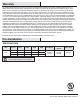
Warranty The supplier warrants the fan motor to be free from defects in workmanship and material present at time of shipment from the factory for a lifetime after the date of purchase by the original purchaser. The supplier also warrants that all other fan parts, excluding any glass or acrylic blades, to be free from defects in workmanship and material at the time of shipment from the factory for a period of two years after the date of purchase by the original purchaser.
Pre-Installation (continued) TOOLS REQUIRED Phillips screwdriver Flat blade screwdriver Adjustable wrench Step ladder HARDWARE INCLUDED NOTE: Hardware not shown to actual size.
Pre-Installation (continued) PACKAGE CONTENTS D A E B F C Part Description G Quantity A Slide-on mounting bracket (inside canopy) 1 B Fan-motor assembly 1 C Blade 5 D Light kit fitter assembly (LED included) 1 Part Description Quantity E Glass bowl 1 F Receiver 1 G Transmitter (battery included) 1 IMPORTANT: This product and/or components are governed by one or more of the following U.S.
Installation MOUNTING OPTIONS WARNING: To reduce the risk of fire, electric shock or personal injury, mount to outlet box marked “Acceptable for fan support of 35 lbs. (15.9 Kg) or less”, and use screws provided with the outlet box. An outlet box commonly used for the support of lighting fixtures may not be acceptable for fan support and may need to be replaced. If in doubt, consult a qualified electrician.
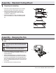
Assembly - Standard Ceiling Mount 1 Preparing for mounting □□ Remove the canopy ring (EE) from the fan motor assembly A CC (B) by turning the ring counterclockwise until it unlocks. □□ Remove the mounting bracket (A) from the fan motor □□ DD B assembly (B) by loosening the two canopy screws (CC) located in the “L shaped” slots. Remove and save the two canopy screws (DD) in the round holes. This will enable you to remove the mounting bracket (A).
Assembly - Hanging the Fan (continued) 3 WARNING: The hook (FF) is only to balance the fan while making the electrical connections. Failure to hang as shown may result in the hook (FF) breaking, causing the fan to fall. The hook must pass from the inside to the outside of the canopy. NOTE: The frequencies on your receiver and hand unit have been preset at the factory. Before installing the receiver, make sure the dip switches on the receiver and hand unit are set to the same frequency.
Assembly - Hanging the Fan (continued) 4 5 Installing the receiver WARNING: To reduce the risk of fire or electric shock, remember to disconnect power. The electrical wiring must meet all local and national electrical code requirements. The electrical source and fan must be 110/120 volt, 60Hz. Do not use this product in conjunction with any variable wall control. Incorrect wire connection can damage this receiver.
Assembly - Hanging the Fan (continued) 6 7 Making the electrical connection WARNING: Each wire not supplied with this fan is designed to accept up to one 12-gauge house wire and two wires from the fan. If you have larger than 12-gauge house wiring or more than one house wire to connect to the fan wiring, consult an electrician for the proper size wire nuts to use. Mounting the fan-motor assembly WARNING: The locking slots of ceiling canopy are provided only as an aid to mounting.
Assembly - Hanging the Fan (continued) 8 9 Attaching the fan blades □□ Attach a blade (C) to the fan-motor housing (B) by inserting □□ Attaching the light kit fitter assembly □□ Attach the light kit fitter assembly (D), remove the one the blade (C) into slots in the side of the fan motor housing (B) and aligning the three screw holes in the blade with the holes in the center flywheel and secure with screws (AA). Make sure all the screws are firmly tightened.
Assembly - Hanging the Fan (continued) 10 Installing the glass bowl WARNING: To reduce the risk of injury, allow the glass to cool completely before removing. □□ Place the bowl (E) into the light kit fitter assembly (D), □□ by aligning the three flat areas on the top flange of the bowl (E) with the three raised dimples in the light kit fitter assembly (D). Turn the shade clockwise until it stops. D E Operating Your Fan and Remote Control 1. Power ON/OFF.
Operating Your Fan and Remote Control (continued) Remote Control - Your fan is equipped with a remote control to operate the speed and lights of your new ceiling fan. A. Warm weather Speed setting for warm or cool weather depend on factors such as the room size, ceiling height, number of fans and so on. A. Warm weather - (Forward) A downward airflow creates a cooling effect. This allows you to set your air conditioner on a higher setting without affecting your comfort. B.
Care and Cleaning WARNING: Make sure the power is off before cleaning your fan. □□ Because of the fan’s natural movement, some connections may become loose. Check the support connections, brackets, and blade attachments twice a year. Make sure they are secure. It is not necessary to remove the fan from the ceiling. □□ Clean your fan periodically to help maintain its new appearance over the years.
This equipment has been tested and found to comply with the limits for a Class B digital device, pursuant to Part 15 of the FCC Rules. These limits are designed to provide reasonable protection against harmful interference in a residential installation. This equipment generates, uses and can radiate radio frequency energy and, if not installed and used in accordance with the instructions, may cause harmful interference to radio communications.