
Installation Guide


10
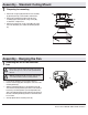
Assembly - Hanging the Fan (continued)
Outlet box
in the ceiling
(GG)
Receiver (F)
Blue
Receiver
Antenna
Black White
Green
BB (x3)
1 2 3 4
ON
DIP
Making the electrical connection
6
IMPORTANT: Use the plastic wire connectors (BB) supplied with
your fan. Secure the connectors with electrical tape and ensure
there are no loose strands or connections.
WARNING: Each wire not supplied with this fan is designed to
accept up to one 12-gauge house wire and two wires from the
fan. If you have larger than 12-gauge house wiring or more
than one house wire to connect to the fan wiring, consult an
electrician for the proper size wire nuts to use.
□ Connect the fan motor white wire to the receiver white wire
using a wire connecting nut (BB).
□ Connect the fan motor black wire to the receiver black wire
using a wire connecting nut (BB).
□ Connect the fan motor blue wire to the receiver blue wire
using a wire connecting nut (BB).
□ Secure each wire connecting nut using electrical tape.
□ Turn the wire connecting nut (BB) upward and push the wiring
into the outlet box (GG).
Mounting the fan-motor assembly
□ Align the locking slots of the fan-motor assembly (B) with the
two screws (CC) in the slide-on mounting bracket (A). Push up
to engage the slots, and turn clockwise to lock the fan-motor
assembly (B) in place.
□ Firmly tighten the two mounting screws (CC).
□ Install the two mounting screws (saved from Assembly Step
1 “Preparing for mounting”) into the holes in the fan-motor
assembly (B) and tighten rmly.
□ Install the decorative canopy ring (EE) by aligning the ring’s
slots with the screws in the fan-motor assembly (B). Rotate
the canopy ring (EE) counterclockwise to lock it in place.
B
EE
A
CC
7
WARNING: The locking slots of ceiling canopy are provided only
as an aid to mounting. Do not leave the fan assembly unattended
until all four canopy screws are engaged and rmly tightened.