Item Model # 1001-801-723 # 253-77-70 USE AND CARE GUIDE JAMERSON MANOR COLLECTION: ELECTRIC FIREPLACE MEDIA MANTEL IMPORTANT INSTRUCTIONS PLEASE READ THIS MANUAL BEFORE INSTALLING AND USING APPLIANCE WARNING! IF THE INFORMATION IN THIS MANUAL IS NOT FOLLOWED EXACTLY, AN ELECTRICAL SHOCK OR FIRE MAY RESULT CAUSING PROPERTY DAMAGE, PERSONAL INJURY OR LOSS OF LIFE. INSTALLER: Leave this manual with the appliance. CONSUMER: Retain this manual for future reference.
Table of Contents Table of Contents. . . . . . . . . . . . . . . . . . . . . . . . . . . . . . . . . . . . . 2 Warranty . . . . . . . . . . . . . . . . . . . . . . . . . . . . . . . . . . . . . . . . . . . 2 Pre-Assembly . . . . . . . . . . . . . . . . . . . . . . . . . . . . . . . . . . . . . . . 3 Planning Assembly. . . . . . . . . . . . . . . . . . . . . . . . . . . . . . . . . . 3 Tools Required . . . . . . . . . . . . . . . . . . . . . . . . . . . . . . . . . . . . . 3 Hardware Included. . . . . . . .
Pre-Assembly VVV PLANNING ASSEMBLY Before you begin assembly, locate the instructions and hardware. Compare all parts with the Hardware Included and Package Contents lists. Be sure you have all the parts and can identify them. A helping hand is always good. Assemble your mantel with an adult assistant if possible. Some pieces are heavy and will need to be held by a helper. Assembly time will take approximately 30-60 minutes. Before assembly, use scissors to unwrap the parts from the packaging.
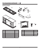
Pre-Assembly (continued) PACKAGE CONTENTS A B C E D F G I H Part Description Quantity Part Description J Quantity A Top Panel 1 G Base Cabinet 1 B Upper Left Side Panel 1 H Firebox 1 C Upper Right Side Panel 1 I Remote Control 1 D Upper Back Panel 2 J Button Cell Battery 1 E Upper Back Panel Support 1 F Adjustable Shelf 2 4
Assembly the side panels and support 1 Installing □□ Locate the left and right upper side panels (B & C) and the upper back panel support (E) and place on a soft surface to protect the finish. AA BB B CC □□ Insert six wood dowels (CC) in the unthreaded holes on the top of the base cabinet (G). E □□ Line up the holes in the left upper side panel (B) with the threaded holes on the top left hand side of the base cabinet (G).
Assembly (continued) the upper back panel support 3 Attaching A □□ Attach the upper back panel support (E) by inserting two bolts (AA) through two washers (BB) into the threaded holes in the upper back panel support (E). Turn the bolts (AA) clockwise to tighten. Do not strip the bolts (AA) by overtightening. E the back panel 4 Attaching □□ Locate the back panels (D) and line them up to the back of the media console with the finished side facing in.
Assembly (continued) the shelves 5 Installing □□ Locate the two shelves (F) and place them on a soft surface to protect the finish. □□ Insert the 8 shelf pins (DD) into the interior of the base cabinet (G) storage areas. Be sure to insert the pins parallel to one another to ensure the shelves (F) are level. G □□ Insert the shelves (F) onto the shelf pins (DD) with the finished side visible.
Assembly (continued) 7 A ttaching the firebox □□ Push the firebox back through the front opening until the metal trim of the firebox (H) is flush with the base cabinet. □□ Once the firebox is in position attach the two mounting brackets included with the firebox (H) by inserting and tightening four screws through the mounting brackets into the firebox (H) and the base (G). □□ H Do not strip the screws by overtightening.
Troubleshooting If you have any questions regarding the product, please call Home Depot Customer Service, 1-800-986-3460, 8 a.m. –7 p.m. EST, Monday – Friday, 9 a.m. - 6 p.m., EST, Saturday. Problem Possible Cause Solution The fireplace does not operate. □□ The fireplace is not plugged in. □□ Make sure the fireplace is plugged in to a standard 120V outlet. □□ A circuit breaker is tripped or a fuse blown.
Care & Cleaning □□ Always turn the heater OFF and unplug the power cord from the outlet before cleaning. □□ Cleaning of the control panel, located in the upper right-hand corner of the fireplace behind the sliding control panel cover, is to be done only using a soft cloth, slightly dampened in water (if needed, a small amount of dish soap can be added to the water) and dried using a clean, dry soft cloth. Cleaning of the screen diffuser is to be done using only water and lint free cloth.
Service Parts C B A E D F G H Part Description Quantity Part Number 253-77-70 Mahogany Finish A Top Panel 1 20-06-073 B Upper Left Side Panel 1 20-06-074 C Upper Right Side Panel 1 20-06-075 D Upper Back Panel 2 20-06-076 E Upper Back Panel Support 1 20-06-077 F Adjustable Shelf 2 20-06-078 G Base Cabinet 1 20-06-079 H Firebox 1 25-900-003 I Firebox Remote Control 1 EF33510AS-15 Hardware Pack 1 20-09-552 Manual 1 253-77-70 11 I HOMEDEPOT.
Questions, problems, missing parts? Before returning to the store, call Home Decorators Collection Customer Service 8 a.m. - 7 p.m., EST, Monday-Friday, 9 a.m. - 6 p.m., EST, Saturday 1-800-986-3460 HOMEDEPOT.COM/HOMEDECORATORS Retain this manual for future use. Manufactured by: GHP Group, Inc. • 6440 W. Howard St.
Núm. de artículo # 1001-801-723 Núm. de modelo # 253-77-70 GUÍA DE USO Y CUIDADO COLECCIÓN JAMERSON MANOR: CHIMENEA ELÉCTRICA CON REPISA INSTRUCCIONES IMPORTANTES POR FAVOR, LEA ESTE MANUAL ANTES DE LA INSTALACIÓN Y USO DEL DISPOSITIVO ¡ADVERTENCIA! SI LA INFORMACIÓN EN ESTE MANUAL NO SE SIGUE CON EXACTITUD, PUEDE RESULTAR UN CHOQUE ELÉCTRICO O INCENDIO OCASIONANDO DAÑOS A LA PROPIEDAD, LESIONES PERSONALES O LA MUERTE. INSTALADOR: Deje este manual con el dispositivo.
Tabla de contenido Tabla de contenido . . . . . . . . . . . . . . . . . . . . . . . . . . . . . . . . . . 14 Garantía. . . . . . . . . . . . . . . . . . . . . . . . . . . . . . . . . . . . . . . . . . . 14 Pre-ensamblaje. . . . . . . . . . . . . . . . . . . . . . . . . . . . . . . . . . . . . 15 Planificación del ensamblaje. . . . . . . . . . . . . . . . . . . . . . . . . 15 Herramientas necesarias. . . . . . . . . . . . . . . . . . . . . . . . . . . . 15 Piezas incluidas. . . . . . . . . . . . . . . . . .
Pre-ensamblaje VVV PLANIFICACION DEL ENSAMBLAJE ntes de iniciar el ensamblaje localice las instrucciones y las piezas. Compare todas las piezas con la lista de piezas incluidas y contenido A del embalaje. Asegúrese de tener todas las piezas y de que pueda identificarlas. Siempre es bueno contar con ayuda. Ensámblelo con asistencia de una persona adulta si es posible. Algunas piezas son pesadas y necesitará ayuda. El tiempo de ensamblaje se estima entre 30-60 minutos.
Pre-ensamblaje (continuación) CONTENIDO DEL PAQUETE A B C E D F G I H Pieza Descripción Cantidad Pieza J Descripción Cantidad A Panel del tope 1 G Mueble de base 1 B Panel lateral superior izquierdo 1 H Cámara de combustión 1 C Panel lateral superior derecho 1 I Control remoto de la cámara de combustión 1 D Panel trasero superior 2 J Batería de botón 1 E Soporte del panel trasero superior 1 F Repisa ajustable 2 16
Ensamblaje de los paneles laterales y 1 Instalación soporte AA BB B □□ Localice los paneles laterales superiores izquierdo y derecho (B y C) y el soporte del panel trasero superior (E) y colóquelo sobre una superficie suave para proteger el acabado. CC E □□ Inserte seis espigas de madera (CC) en los orificios no roscados sobre el tope del mueble de base (G).
Ensamblaje (continuación) del soporte del panel 3 Colocación trasero superior A □□ Coloque el soporte del panel trasero superior (E) insertando dos pernos (AA) a través de dos arandelas (BB) en los orificios roscados en el soporte del panel trasero superior (E). Gire los pernos en el sentido de las agujas del reloj para apretar. No apriete los pernos (AA) en exceso ya que podría dañarlos.
Ensamblaje (continuación) de las repisas 5 Inserción □□ Localice las dos repisas (F) y colóquelas sobre una superficie suave para proteger el acabado. □□ Inserte las 8 clavijas de repisa (DD) en el interior de la cabina (G). Asegúrese de insertar las clavijas paralelas entre sí para asegurar que las repisas queden niveladas. G □□ Inserte las repisas (F) sobre las clavijas de repisa (DD) dejando visibles las caras con acabado.
Ensamblaje (continuación) olocación de la cámara de 7 C combustión □□ Empuje la cámara de combustión a través de la apertura frontal hasta que la moldura de metal de la cámara de combustión (H) esté al ras con el mueble de base. □□ Una vez que la cámara de combustión esté en su posición coloque los dos soportes de montaje incluidos con la cámara de combustión (H) insertando y apretando cuatro tornillos a través de los soportes de montaje en la cámara de combustión (H) y la base (G).
Resolución de fallas Si tiene preguntas respecto al producto, llame a Servicio al Cliente de Home Decorators al 1-800-986-3460, 8 a.m. - 7 p.m., Hora del Este de lunes a viernes, 9 a.m. - 6 p.m., Hora del Este de Sábado Problema Causa posible La chimenea no funciona. □□ La chimenea no está enchufada. Solution □□ Un disyuntor de circuito se ha activado o un fusible ha explotado. □□ El interruptor ON/OFF está defectuoso. La luz de energía está encendida pero el efecto de la llama no es visible.
Cuidado y limpieza □□ Siempre apague el calefactor y desconecte el cable eléctrico del tomacorriente antes de limpiarlo. □□ La limpieza del panel de control, localizado en la esquina superior derecha de la chimenea, debe hacerse usando solamente un paño suave, ligeramente humedecido en agua (de ser necesario, se puede agregar una pequeña cantidad de jabón de platos al agua) y secarse usando un paño suave limpio y seco.
Piezas de servicio C B A E D F G H Pieza Descripción Cant.
¿Preguntas, problemas o partes faltantes? Antes de regresar a la tienda, llame al servicio de atención al cliente de Home Decorators Collection 8 a.m. - 7 p.m., Hora del Este de lunes a viernes, 9 a.m. - 6 p.m., Hora del Este de Sábado 1-800-986-3460 HOMEDEPOT.COM/HOMEDECORATORS Guarde este manual para futuras referencias. Fabricado por: GHP Group, Inc. • 6440 W. Howard St.