326 314/78646/25MM4495-PC72 XXX XXX/80434/25MM4495-PB84 XXX XXX/82612/25MM4495-PM83 USE AND CARE GUIDE GRAND HAVEN ELECTRIC FIREPLACE Questions, problems, missing parts? Before returning to the store, call Home Decorators Collection Customer Service 8 a.m. - 6 p.m., EST, Monday - Friday 1-800-986-3460 HOMEDEPOT.COM//HOMEDECORATORS THANK YOU We appreciate the trust and confidence you have placed in Home Decorators through the purchase of this electric fireplace.
Table of Contents Maximum Load Warning............................................ 2 Safety Information...................................................... 3 Warranty...................................................................... 4 Pre-Assembly.............................................................. 5 Hardware Included ................................................... 5 Product Specifications........................................................ 5 Tools Required...........................
Safety Information Important Safety Instructions Please read and understand this entire manual before attempting to assemble, operate or install the product. If you have any questions regarding the product, please call customer service at 1-800-986-3460, 8 a.m.-6 p.m., EST, Monday-Friday. When using electrical appliances, always follow basic precautions to reduce the risk of fire, electrical shock, and injury to persons, including the following: 1. Read all instructions before using this appliance. 2.
Warranty 1 Year Limited Warranty: The manufacturer warrants this product to be free from manufacturing and material defects for a period of one year from date of purchase, subject to the following conditions and limitations: 1. Install and operate this Electric Fireplace in accordance with the installation and operating instructions furnished with the product at all times. Any unauthorized repair, alteration, willful abuse, accident, or misuse of the product shall nullify this warranty. 2.
Pre-Assembly HARDWARE INCLUDED H-2 H-1 AA II BB CC JJ Part AA BB CC DD EE FF GG HH II JJ KK LL MM NN OO ZZ DD LL KK FF EE MM Description Large Bolt Washer Wood Dowel Small Bolt Shelf Pin Screw with Washer Head Knob (with screws, not to scale) Euro Hinge (not to scale) Large Flathead Screw Small Flathead Screw Tipping Restraint Hardware Plastic Connector 2 Hole Block (pre-attached) Plastic Connector 3 Hole Block (pre-attached) Leveler (pre-attached) Connection Plate (pre-attached) Touch-up Pen
Pre-Assembly (continued) PACKAGE CONTENTS NOTE: All panels are labeled left and right as viewed from the front of unit.
Assembly 1 2 Attaching the Front Panel Set the Center Shelf (K) down on a scratch-free surface. Screw the Small Bolts (DD) through the Plastic Connector (LL) to the Center Shelf (K). Attaching the Side Panels Attach the Center Left Side Panel (B) and Center Right Side Panel (C) to the Center Shelf (K) using Plastic Connector 2 Hole Block (LL) and Small Bolts (DD).
Assembly (continued) 4 5 Attaching the hinges Attach the Hinge Bracket (H-1) to the Right Side Panel (F). Use a Phillips head screwdriver to tighten the Flathead Screw (JJ) through the pre-drilled holes. Repeat for the Left Side Panel (E). Installing the feet Insert Wood Dowels (CC) into the holes on the Base (A). Push the Left Foot (O) and Right Foot (P) snug to the Hearth/Base (A). Insert Large Bolts (AA) through the Washers (BB) and into the pre-drilled holes in the Base (A) and tighten.
Assembly (continued) 7 8 Installing the side panels Attach the completed assembly from step 3 to the Base (A). Insert Small Bolts (DD) through the holes in the Plastic Connector (MM) and tighten. Insert one Wood Dowel (CC) into the pre-drilled holes in the base assembly. Push the Right Side Panel (F) and Left Side Panel (E) snug to the Base (A). Insert Bolts (DD) through the holes in the Plastic Connector (MM) and tighten.
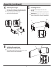
Assembly (continued) 10 Installing the top 11 Installing the back panels Place Wood Dowels (CC) into the pre-drilled holes located on top of the Left Side Panel (E) and Right Side Panel (F). Place the Top (G) on top of the completed assembly. From the inside, attach the Top (G) using Small Bolts (DD) through the holes in the Plastic Connector (MM). Use a Phillips head screwdriver to tighten all Small Bolts (DD).
Assembly (continued) 13 Attaching the knobs 14 Installing the doors Remove the presassembled screw from the Door Knobs (GG), then attach the Door Knob (GG) to the Left Door (L) and the Right Door (M) with the screws. L Align the Hinges (H-2) to the Hinge Brackets (H-1), by sliding the Hinges (H-2) onto the Hinge Brackets (H-1). Tighten the preassembled screw on the Hinge Bracket (H-1) to secure each door in place. Hinges are fully adjustable as shown below.
Assembly (continued) the fireplace insert into 16 Installing the mantel assembly the center securing 17 Attaching block Lift the fireplace insert carefully into the back of the unit and center in the fireplace insert opening. Do not drag the fireplace insert across the Base (A) as it may scratch your unit. Attach the Center Securing Block (R) that holds the fireplace insert from the back by inserting Small Bolts (DD) through the 3 Hole Connector (MM) and into the pre-drilled holes of the panel.
Assembly (continued) 19 Installing the tipping restraint hardware When the Tipping Restraint Hardware Kit (KK) is properly installed, it can provide protection against unexpected tipping of the Unit due to small tremors, bumps or climbing. Your Unit comes with two Tipping Restraint Hardware Kits (KK). Each Tipping Restraint Hardware Kit (KK) includes one Unit Anchor, one Wall Anchor, one Anchor Tether, and four Anchor Screws. Use these to complete the following steps for a proper installation.
Operation NOTE: The control panel can be accessed at the upper-right corner of the insert. When a function is changed from the control panel or remote control there will be a corresponding indicator (see Figure 1) on the upper-right of the projection screen. The indicator shows the function changed and the level selected by the control panel or remote control. When the function is turned off, the corresponding indicator will flash several times and then fade off. Fig .
Operation 7 Replacing the remote control battery 8 Disposing of used batteries The battery may contain hazardous substances that could endanger the enviroment and human health. When the remote control stops operating or its range seems reduced, it is time to replace the batteries with new ones. On the back end of the remote, press and slide the battery door open and remove the old batteries. Insert 2 AAA batteries, checking that the + and - sides of the batteries match inside the battery compartment.
FCC/IC Information This equipment has been tested and found to comply with the limits for Class B digital device, pursuant to part 15 of the FCC Rules. These limits are designed to provide reasonable protection against harmful interference in a residential installation.
Troubleshooting PROBLEM POSSIBLE CAUSE CORRECTIVE ACTION The display shows “E1”. The thermostat sensor is broken or disconnected. Unplug the fireplace, remove the back panel of the fireplace and check that the thermostat is plugged into the main circuit board. If this does not solve the problem contact customer service for a replacement thermostat sensor. The display shows “E2”. The thermostat sensor is broken. Contact customer service for a replacement thermostat sensor.
Replacement Parts For replacement parts, call our customer service department at 1-800-986-3460, 8 a.m.-6 p.m., EST, Monday-Friday. Part Description Qty. A Heater/Blower Assembly 1 B Main Circuit Board 1 C Flame Generator / Spinner 1 D Flame Generator Drive Motor 1 E LCD Display 1 F Front Projection Screen 1 G Flame Circuit Board 1 H Emberbed with Log 1 I Control Panel Circuit Board 1 J Control Panel Buttons 1 K Remote Control 1 K 18 HOMEDEPOT.
Questions, problems, missing parts? Before returning to the store call Home Depot Customer Service 8 a.m. - 6 p.m., EST, Monday-Friday 1-800-986-3460 HOMEDEPOT.COM/HOMEDECORATORS RETAIN THIS MANUAL FOR FUTURE USE.