
Installation Guide


Page 6
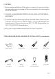
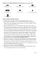
PARTS INCLUDED FOR INSTALATION (parts are not to scale):
1 Green Ground Screw (#18)
2 Mounting Screw (#12)
2 Outlet Box Screw (#13)
2 Lock Knob (#19)
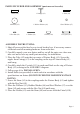
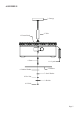
INSTALATION INSTRUCTIONS:
1. Unscrew the Lock Knobs (#19) from the Mounting Screw (#12).
2. Attach the Circular Strap (#16) to the Outlet Box using two Outlet Box
Screws (#13). The side of the Circular Strap with “GND” marked on it and
two convex points must face out.
3. While holding the Canopy (#3) toward the ceiling, connect the white wire
from the xture to the Neutral wire from the Outlet Box (#14) and the black
wire from the xture to the hot wire from the Outlet Box (#14). Cover the
two wire connections using the two provided Wire Connectors (#15). Wrap
the two wire connections with electrical tape for a more secure connection. If
your outlet box has a ground wire (green or bare copper), connect xture’s
ground wire to it using the wire Connector (#15). Otherwise connect the
copper ground wire from the xture to Green Ground Screw (#18) on the
Circular Strap (#16). Note: If you have electrical questions, consult your
local electrical code for approved grounding methods.
4. Mount the Canopy (#3) of the xture by aligning the protruding Mounting
Screws (#12) all the way through the holes on the Canopy (#3). Be careful
not to pinch any of the wires between the xture and the Outlet Box (#14).
Tighten the xture to the ceiling by screwing the two Lock Knobs (#19) onto
the two protruding Mounting Screws (#12).
5. Follow Page 4 for the remaining ASSEMBLY.
6. Installation is completed. Turn on the power at the circuit breaker or fuse
box. Turn the light switch on to activate the xture.
3 Wire Connector (#15)
1 Circular Strap (#16)
2 Hex Nut (#17)