Item #1003 316 478, 1003 316 497 Model #51847, 51848 UL Model #EF200S(R)-54 USE AND CARE GUIDE CONNOR 54-INCH CEILING FAN Questions, problems, missing parts? Before returning to the store, call Home Decorators Collection Customer Service 8 a.m. - 7 p.m., EST, Monday-Friday, 9 a.m. - 6 p.m., EST, Saturday 1-800-986-3460 HOMEDEPOT.COM/HOMEDECORATORS To view an instructional video on how to install this product: 1. Go to www.homedepot.
Table of Contents Table of Contents ................................................................ 2 Assembly .............................................................................. 7 Safety Information ............................................................... 2 Operation ........................................................................... 14 Warranty ............................................................................... 3 Care and Cleaning ...............................
Warranty The supplier warrants the fan motor to be free from defects in workmanship and material present at time of shipment from the factory for a lifetime after the date of purchase by the original purchaser. The supplier also warrants that all other fan parts, excluding any glass or acrylic blades, to be free from defects in workmanship and material at the time of shipment from the factory for a period of two years after the date of purchase by the original purchaser.
Pre-Installation (continued) HARDWARE INCLUDED NOTE: Hardware not shown to actual size.
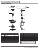
Pre-Installation (continued) PACKAGE CONTENTS A H B I C D J K E L F M G Part Description Quantity Part Description Quantity H Blade 5 A Slide-on mounting bracket (inside canopy) 1 I Blade arm 5 B Canopy 1 J LED bulb 2 C Canopy bottom cover 1 K Remote control (battery included) 1 D Ball/downrod assembly 1 L Receiver 1 E Fan-motor assembly 1 M Wall bracket 1 F Light kit fitter assembly 1 G Glass bowl 1 IMPORTANT: This product and/or components are governed
Installation MOUNTING OPTIONS NOTE: You may need a longer downrod to maintain proper blade clearance when installing on a steep, sloped ceiling. The maximum angle allowable is 30° away from horizontal. WARNING: To reduce the risk of fire, electric shock, or personal injury, mount the fan to an outlet box marked “Acceptable for fan support of 35 lbs. (15.9kg) or less” and use the screws provided with the outlet box.
Assembly - Standard Ceiling Mount 1 Preparation for standard mounting 2 □ Remove the canopy bottom cover (C) from the canopy (B) by □ □ □ turning the bottom cover counterclockwise until it unlocks. Loosen the two canopy screws (FF) located in the bottom of the mounting bracket (A), and turn the canopy counterclockwise to remove the mounting bracket (A) from the canopy (B).
Assembly - Hanging the Fan 1 2 Attaching the fan to the electrical box Hanging the fan WARNING: To reduce the risk of fire, electric shock, or other personal injury, mount the fan to an outlet box or supporting system marked “Acceptable for fan support of 35 lbs. (15.9kg) or less” and use the mounting screws provided with the outlet box. WARNING: When using the standard ball/downrod mounting, the tab in the ring at the bottom of the mounting bracket must rest in the groove of the hanger ball.
Assembly - Hanging the Fan (continued) 3 4 Installing the receiver Wiring the receiver to the household wiring WARNING: To reduce the risk of fire or electric shock, remember to disconnect power. The electrical wiring must meet all local and national electrical code requirements. The electrical source and fan must be 110/120 volt, 60Hz. Do not use this product in conjunction with any variable wall control. Incorrect wire connection can damage this receiver.
Assembly - Hanging the Fan (continued) 5 6 Wiring the fan to the receiver □ Align the locking slots of the canopy (B) with the two screws NOTE: The fan comes with 12 in. lead wires for use with the provided 4.5 in. ball downrod assembly (D), if you wish to use longer downrod, you can use the extension lead wire (42 in.) (AA) provided. □ □ If using the 4.5 in.
Assembly - Attaching the Blades 1 2 Attaching the blade bracket NOTE: This fan features QuickInstallTM blades for fast and easy blade installation. □ Fasten the blade bracket (I) to the motor (E) by inserting the □ Attaching the fan blades alignment post into the slot on the bottom of the fan-motor assembly (E) and tightening the motor screws (GG) that are pre-assembled to the blade bracket (I). Repeat for the remaining four blade brackets (I).
Assembly - Attaching the Light Kit 1 2 Attaching the light kit CAUTION: Make sure the power is off before attaching or removing the glass bowl. CAUTION: To reduce the risk of electric shock, disconnect the electrical supply circuit to the fan before installing the light kit. □ Remove and save the three screws (HH) from the light kit □ □ Installing the glass bowl WARNING: Allow the glass bowl to cool completely before removing. fitter assembly (F).
Assembly - Attaching the Fan without the Light Kit 1 Assembling the fan without the light kit NN □ In order to use the fan without the light kit, remove the switch □ □ □ cap (WW) from the top of the light kit fitter assembly (F) by removing the center hex nut (NN) inside the switch cap (WW), and then thread the switch cap (WW) off the threaded nipple on the top of the light kit fitter assembly (F). Press the plastic plug (PP) (provided) into the center hole of the switch cap (WW).
Preparing the Remote Control Pairing the Remote Control NOTE: The remote control has already been paired to the ceiling fan for your convenience. If you have two of the same model fans in your home, please follow the steps below to control each fan independently. □ Confirm that the power to the fan is off at either the wall switch or breaker box. □ Return power to the fan at the wall switch or breaker box. □ Install one 3V Lithium Battery (included).
Operating Your Fan Your fan is equipped with a remote control to operate the fan speed and lights of your new ceiling fan. The appropriate speed settings for warm or cool weather depends on factors such as the room size, ceiling height, and number of fans. The fan is shipped from the factory with the reversing switch positioned to circulate air downward.
Care and Cleaning WARNING: Make sure the power is off before cleaning your fan. □ Because of the fan’s natural movement, some connections may become loose. Check the support connections, brackets, and blade attachments twice a year. Make sure they are secure. It is not necessary to remove the fan from the ceiling. □ Clean your fan periodically to help maintain its new appearance over the years.
Questions, problems, missing parts? Before returning to the store, call Home Depot Customer Service 8 a.m. - 7 p.m., EST, Monday-Friday, 9 a.m. - 6 p.m., EST, Saturday 1-800-986-3460 HOMEDEPOT.COM/HOMEDECORATORS Retain this manual for future use.
Artículo # 1003 316 478, 1003 316 497 Modelo # 51847, 51848 Modelo UL #EF200S(R)-54 GUÍA DE USO Y MANTENIMIENTO VENTILADOR DE TECHO CONNOR, 54 PLG (1.3 M) ¿Preguntas, problemas o piezas en falta? Antes de devolver a la tienda, llamar al servicio al cliente de Home Decorators Collection. De lunes a viernes, entre 8:00 a.m. y 7:00 p.m. (Este), y los sábados de 9:00 a.m. a 6:00 p.m. (Este). 1-800-986-3460 HOMEDEPOT.COM/HOMEDECORATORS To view an instructional video on how to install this product: 1.
Tabla de contenido Tabla de contenido .............................................................. 2 Ensamblaje........................................................................... 7 Información de seguridad................................................... 2 Funcionamiento ................................................................. 14 Garantía ................................................................................ 3 Mantenimiento y limpieza .....................................
Garantía El proveedor garantiza de por vida, a partir de la fecha de adquisición por el comprador original, que el motor del ventilador no presenta defectos de fabricación ni de materiales al momento del envío desde la fábrica.
Preinstalación (continuación) SE INCLUYEN LOS HERRAJES NOTA: Los herrajes no se muestran en tamaño real.
Preinstalación (continuación) CONTENIDO DEL PAQUETE A H B I C D J K E L F M G Pieza Descripción Cantidad Pieza Descripción Cantidad H Aspa 5 A Soporte de montaje deslizante (dentro de la cubierta) 1 I Brazo del aspa 5 B Cubierta 1 J Bombilla LED 2 C Tapa del fondo de la cubierta 1 K Control remoto (incluye batería) 1 D Conjunto del tubo bajante/bola 1 L Receptor 1 E Conjunto motor-ventilador 1 M Soporte de pared 1 F Conjunto del soporte del kit de luces 1 G
Instalación OPCIONES DE MONTAJE ADVERTENCIA: Para reducir el riesgo de incendio, descarga eléctrica o lesiones personales, instalar en una caja eléctrica clasificada como “apropiada para sostener ventiladores de 35 lb (15.9 kg) o menos” y usar los tornillos que vienen con ella. Una caja eléctrica utilizada comúnmente para soporte de lámparas puede no servir como soporte de ventilador y tal vez deba reemplazarse. En caso de duda, consultar a un electricista calificado.
Ensamblaje - Montaje estándar en techo 1 2 Preparación para montaje estándar □ Retirar la tapa inferior (C) de la cubierta (B) girándola hacia la □ □ izquierda hasta liberarla. Aflojar los dos tornillos de la cubierta (FF) en la parte inferior del soporte de montaje (A) y girar la cubierta hacia la izquierda para quitar aquel (A) de esta (B).
Ensamblaje - Cómo colgar el ventilador 1 2 Cómo fijar el ventilador a la caja eléctrica Cómo colgar el ventilador ADVERTENCIA: Para reducir el riesgo de incendio, descarga eléctrica o lesiones personales, instalar sólo en una caja eléctrica o sistema de soporte clasificado como “apropiado para sostener ventiladores de 35 lb (15.9 kg) o menos”, y usar sólo los tornillos de montaje incluidos con la caja eléctrica.
Ensamblaje - Cómo colgar el ventilador (continuación) 3 4 Cómo instalar el receptor Cómo cablear el receptor al cableado del hogar ADVERTENCIA: Para reducir el riesgo de incendio o de descarga eléctrica, recuerda desconectar la electricidad. El cableado eléctrico tiene que cumplir todos los requisitos de los códigos eléctricos nacionales y locales. La fuente de energía y el ventilador tienen que ser de 110/120 V y 60 Hz. No utilizar este producto con ningún control variable de pared.
Ensamblaje - Cómo colgar el ventilador (continuación) 5 6 Cómo cablear el ventilador al receptor □ Alinear las ranuras de cierre de la cubierta (B) con los dos tornillos (FF) NOTA: El ventilador viene con cables terminales de 12 plg (30.5 cm) para usar con el conjunto del tubo bajante/bola (D) de 4.5 plg (11.4 cm); si se desea un tubo bajante más largo, puede usarse la extensión de cable conector de 42 plg (1.07 m) (L) incluida. □ □ Al usar el conjunto del tubo bajante/bola (D) de 4.5 plg (11.
Ensamblaje — Cómo montar las aspas 1 2 Cómo montar el soporte de aspas □ Ajustar el soporte del aspa (I) al motor (E) insertando el poste □ Cómo fijar las aspas del ventilador NOTA: Este ventilador viene con aspas QuickInstallTM para su rápida y fácil instalación. de alineación dentro de la ranura de la parte inferior del conjunto motor-ventilador (E) y ajustando los tornillos del motor (GG), que están preensamblados, al soporte de aspa (I).
Ensamblaje - Cómo instalar el kit de luces 1 2 Cómo instalar el kit de luces PRECAUCIÓN: Asegurar que la corriente esté cortada antes de montar o retirar el tazón de vidrio. PRECAUCIÓN: Para disminuir el riesgo de descarga eléctrica, desconectar el circuito de energía del ventilador antes de instalar el kit de luces. □ Quitar y guardar los tres tornillos (HH) del conjunto del □ □ Cómo instalar el tazón de vidrio ADVERTENCIA: Esperar que el tazón de vidrio se enfríe completamente antes de retirarlo.
Ensamblaje - Cómo instalar el ventilador sin el kit de luces 1 Cómo ensamblar el ventilador sin el kit de luces NN □ Para usar el ventilador sin el kit de luces, retirar la cubierta de □ □ □ la caja del interruptor (WW) de la parte superior del conjunto del soporte del kit de luces (F) quitando la tuerca hexagonal del centro (NN) dentro de dicha cubierta (WW) y desenroscándola (WW) de la boquilla roscada en la parte superior del conjunto del soporte del kit de luces (F).
Cómo preparar el control remoto Cómo configurar el control remoto NOTA: El control remoto ya ha sido configurado con el ventilador de techo para tu conveniencia. Si tienes dos ventiladores del mismo modelo en tu hogar, sigue los pasos más abajo para controlar cada ventilador por separado. □ Confirmar que la electricidad del ventilador está desconectada en □ □ □ □ el interruptor de pared o en la caja de cortacircuitos.
Cómo usar el ventilador El ventilador está equipado con un control remoto que controla la velocidad y las luces de tu nuevo ventilador de techo. Las configuraciones de velocidad apropiadas para clima cálido o frío dependen de factores como tamaño de la habitación, altura del techo y cantidad de ventiladores. El ventilador se envía desde la fábrica con el interruptor de reversa en posición de hacer circular el aire hacia abajo.
Mantenimiento y limpieza ADVERTENCIA: Antes de limpiar el ventilador hay que asegurar que la electricidad esté cortada. □ Por causa del movimiento natural del ventilador, algunas conexiones pueden aflojarse. Revisar dos veces al año las conexiones de soporte, los soportes y los accesorios de las aspas. Comprobar que estén seguros. No es necesario desmontar el ventilador del cielo raso. □ Hay que limpiar el ventilador con frecuencia para que luzca como nuevo al paso de los años. No usar agua al limpiarlo.
¿Preguntas, problemas o piezas en falta? Antes de devolver a la tienda, llamar al servicio al cliente de The Home Depot. De lunes a viernes, entre 8:00 a.m. y 7:00 p.m. (Este), y los sábados de 9:00 a.m. a 6:00 p.m. (Este). 1-800-986-3460 HOMEDEPOT.COM/HOMEDECORATORS Conservar este manual para uso futuro.