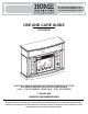
XXX XXX/95575/23MM90141-PW13 XXX XXX/94004/23MM90141-PC78 XXX XXX/95582/23MM90141-PG03 USE AND CARE GUIDE TOLLESON QUESTIONS, PROBLEMS, MISSING PARTS? BEFORE RETURNING TO THE STORE, CALL HOME DECORATORS COLLECTION CUSTOMER SERVICE 8 A.M. - 7 P.M., EST, MONDAY - FRIDAY, 9 A.M. - 6 P.M., EST, SATURDAY 1-800-986-3460 HOMEDEPOT.COM/HOMEDECORATORS THANK YOU We appreciate the trust and confidence you have placed in Home Decorators through the purchase of this electric fireplace.
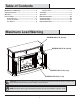
Table of Contents Maximum Load Warning ........................................... 2 Safety Information ..................................................... 3 Warranty ..................................................................... 5 Pre-Assembly............................................................. 6 Hardware Included ................................................... 6 Product Specifications....................................................... 6 Tools Required ............................
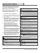
Safety Information Please read and understand this entire manual before attempting to assemble, operate or install the product. If you have any question regarding the product, please call customer service at service at 1-800-986-3460, 8 a.m.-7 p.m., EST, Monday-Friday, 9 a.m. - 6 p.m., EST, Saturday. WARNING: Under no circumstances should this fireplace be modified. Parts that must be removed for servicing must be replaced prior to operating this fireplace again.
Safety Information (continued) NOTE: Use care in assembling your new fireplace. Take your time and use the hardware provided and a quality Phillips head screwdriver. Never overtighten bolts. • Do not sit on any part of the mantel. NOTE: To avoid injury from unexpected starting or electrical shock, do not plug the power cord into a source of power during unpacking and assembly. The cord must remain unplugged whenever you are adjusting/assembling the fireplace.
Warranty Warranty 1 Year Limited Warranty: The manufacturer warrants that your new Electric Fireplace is free from manufacturing and material defects for a period of one year from date of puchase, subject to the following conditions and limitations. 1. Install and operate this appliance in accordance with the installation and operating instructions furnished with the product at all times. Any unauthorized repair, alteration, willful abuse, accident, or misuse of the product shall nullify this warranty. 2.
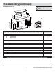
Pre-Assembly HARDWARE INCLUDED AA BB JJ KK CC DD EE MM LL FF NN OO GG HH PP II QQ Part Description Part Number Quantity AA Wood Dowel PH-DWLNTL001 14 BB Small Flathead Screw PH-BLTBLK002 39 CC Shelf Pin PH-SPNPCSPLB2 8 DD Handle (with Screw) N/A 2 EE Short Screw PH-SCRBLK007 38 FF Door Hinge PH-HNGDQB003 4 GG 2 Hole Plastic Connector Block PH-PCBBLK001 18 HH 3 Hole Plastic Connector Block PH-PCBBLK001 1 II Long Screw PH-SCRBLK006 9 JJ Screw PH-SCRBL
Pre-Assembly (continued) PACKAGE CONTENTS NOTE: All panels are labeled left and right as viewed from the front of unit.
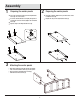
Assembly 1 2 Preparing the center panels Place the Left Center Panel (B) and the Right Center Panel (C) onto a flat surface. Insert the Small Flathead Screws (BB) through the 2 Hole Plastic Connector Blocks (GG) to the Left Center Panel (B). Repeat steps for the Right Center Panel (C). BB Preparing the center panels Insert Wood Dowels (AA) into the pre-drilled holes in the Left Center Panel (B). Repeat this step for the Right Center Panel (C).
Assembly (continued) 4 5 Preparing the upper front panel Attaching the upper front panel Align the Upper Front Panel (D) with the pre-drilled holes in the Left Center Panel (B) and the Right Center Panel (C). Push the Upper Front Panel (D) and the Left Center Panel (B) together. Repeat to connect to the Right Center Panel (C). Place the Upper Front Panel (D) onto a flat surface. Insert Wood Dowels (AA) into the pre-drilled holes.
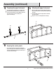
Assembly (continued) 7 8 Securing the upper front panel Align the Metal Plate (OO), pre-attached to the Upper Front Panel (D), with the Left Center Panel (B). Insert the Short Screw (EE) through the Metal Plate (OO). Repeat for the Right Center Panel (C). Preparing the side panels Place the Left Side Panel (E) on a flat surface. Insert the Small Flathead Screws (BB) through the 2 Hole Plastic Connector Blocks (GG). Repeat to prepare the Right Side Panel (F).
Assembly (continued) 10 Preparing the decorative side panel 11 Preparing the divider Place the Decorative Side Panel (I) on a flat surface. Insert Small Flathead Screws (BB) through the 2 Hole Plastic Connector Blocks (GG). Attach two 2 Hole Plastic Connector Blocks (GG) to the Decorative Side Panel (I). Repeat these steps for the Decorative Side Panel (J). GG Insert Small Flathead Screws (BB) through the 3 Hole Plastic Connector Block (HH) and secure to the Divider (K).
Assembly (continued) 13 Preparing the top assembly 14 Preparing the center shelf Insert Wood Dowels (AA) into the pre-drilled holes in the Decorative Side Panels (I,J) and the Divider (K). Place the Center Shelf (H) upside down on a flat surface. Using the Phillips Screwdriver, insert the Screws (MM) through each Magnetic Catch (LL). MM LL J K I AA H 15 Attaching the center shelf Insert Long Screws (II) through the pre-drilled holes in the Center Shelf (H).
Assembly (continued) 16 Attaching the top assembly GG Place the previously assembled Top Assembly (G), Decorative Side Panels (I,J), Divider (K) and the Center Shelf (H) on top of the previously assembled base. From underneath, insert Small Flathead Screws (BB) through the previously attached 2 Hole Plastic Connector Blocks (GG). Secure tightly using a Phillips Screwdriver. BB G J K I H E B C F 17 Preparing the doors Place the Left Door (L), upside down, on a flat surface.
Assembly (continued) 18 Attaching the handles Remove the preassembled screws from the Handles (DD), then attach the Handle (DD) to the Left Door (L) and Right Door (M) with the screws. DD L M 19 Attaching the doors Align the Right Door (M) with the Right Side Panel (F). Insert Screws (JJ) through the previously attached Door Hinges (FF). Repeat to attach the Left Door (L).
Assembly (continued) 20 Installing the back panels Insert the Short Screws (EE) through the pre-drilled holes in the Upper Back Panel (N) and the Side Back Panels (O). N EE O O 21 Attaching the adjustable shelves Insert the Shelf Pins (CC) into the pre-drilled holes on the inside of the Left Side Panel (E) and the Left Center Panel (B). Rest the Adjustable Shelf (P) on the Shelf Pins (CC). Repeat for the right side. B P E P CC 15 HOMEDEPOT.
Assembly (continued) the fireplace insert into 22 Installing the mantel assembly Lift the Fireplace Insert (Q) carefully into the back of the unit and center in the fireplace insert opening. Do not drag the fireplace insert across the Base as it may scratch your unit. Q 23 Securing the fireplace insert Insert the Screw (JJ) through the Angle Bracket (KK) into the pre-drilled hole in the Bottom Base Panel (A).
Assembly (continued) 24 Installing the tipping restraint hardware When the Tipping Restraint Hardware (NN) is properly installed, it can provide protection against unexpected tipping of the Unit due to small tremors, bumps or climbing. Your Unit comes with two Tipping Restraint Hardware (NN). Each Tipping Restraint Hardware (NN) includes one Unit Anchor, one Wall Anchor, one Anchor Tether, and four Anchor Screws. Use these to complete the following steps for a proper installation.
Operation Operation NOTE: The control panel can be accessed at the upper-right corner of the insert. 1 Powering the fireplace 2 Push the Power button to supply power to all functions of the fireplace and put the insert in a standby mode. Push the Power button again to turn off all functions.
Operation (continued) 5 Replacing the remote control battery 6 Disposing of used batteries The battery may contain hazardous substances that could endanger the enviroment and human health. When the remote control stops operating or its range seems reduced, it is time to replace the battery with new ones. On the back end of the remote, press and slide the battery door open and remove the old battery. Insert 2 AAA batteries, checking that the + and sides of the battery match inside the battery compartment.
FCC/IC Information WARNING: Changes or modifications to this unit not expressly approved by the party responsible for compliance could void user’s authority to operate the equipment. NOTE: This equipment has been tested and found to comply with the limits for Class B digital device, pursuant to part 15 of the FCC Rules. These limits are designed to provide reasonable protection against harmful interference in a residential installation.
Troubleshooting PROBLEM ROOT CAUSE CORRECTIVE ACTION Display shows " " The thermostat sensor is broken or disconnected. Unplug the fireplace, remove the back panel of the fireplace and check that the thermostat is plugged into the main circuit board. If this does not solve the problem contact customer service for a replacement thermostat sensor. Display shows " " The thermostat sensor is broken. Contact customer service for a replacement thermostat sensor.
Troubleshooting (continued) PROBLEM Flame effect works but heater function does not and the emberbed flashes when the Heater button is pressed. ROOT CAUSE CORRECTIVE ACTION The heater is disabled. With the power on press and hold the POWER button on the control panel for 10 seconds. Once re-enabled the emberbed lights will flash multiple times. There are no batteries. Change the remote batteries. The signal is poor. Operate remote transmitter at a slow measured pace.
Replacement Parts For replacement parts, call our customer service department at 1-800-986-3460, 8 a.m.-7 p.m., EST, Monday-Friday, 9 a.m. - 6 p.m., EST, Saturday. Part 1 2 3 4 5 6 7 8 9 10 11 12 Description Qty.
Questions, problems, missing parts? Before returning to the store call Home Decorators Customer Service 8 a.m. - 7 p.m., EST, Monday - Friday, 9 a.m. - 6 p.m., EST, Saturday 1-800-986-3460 HOMEDEPOT.COM/HOMEDECORATORS RETAIN THIS MANUAL FOR FUTURE USE.