
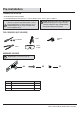
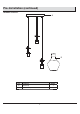
Instructions / Assembly

Installation (continued)
6
4
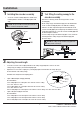
Making the electrical connections
Green ground screw
AA
CC
2
1
□
□
□
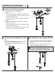
Attaching the xture body to the outlet
box
5
Re-attach the xture body (A) to the crossbar assembly (AA).
Secure with the previously removed hex nut (2).
Then, attach the lock ball (1) over the ceiling canopy of the
xture body (A).
AA
A
A
4
B
6
Installing the shades and the light bulbs
□
□
Unscrew the socket ring (4) from the socket of the xture body
(A). Place the shade (B) over the socket and secure with the
socket ring (4).
Install the correct bulbs (not included) referring to xture
markings and/or labels for maximum wattage.
NOTE: Uses three 60W maximum medium base (E26) type
"S" or type "A" or 9W maximum medium base (E26)
self-ballasted LED vintage Edison bulbs (sold separately).
□
□
□
□
□
□
□
* Use wire connectors (CC) to connect the wires.
Ground Wire:
Wrap the supply ground wire around the green ground screw on
the crossbar assembly (AA), no less than 2 in. from the end of the
wire. Tighten the ground screw.
Connect the xture ground wire to the supply ground wire with a
wire connector (CC).
Supply Wire:
Connect the supply white wire to the white xture supply wire
with a wire connector (CC).
Connect the supply black (or red) wire to the black xture supply
wire with a wire connector (CC).
Wrap each connection with approved electrical tape and carefully
insert all of the connected wires into the outlet box.