Item Model # 1000-050-887 # 658-383 # MTVSC2513SE-2 # MTVSC2513SCH # MFB25WSC-1 Use and Care Guide Silverthorne collection: ELECTRIC FIREPLACE MEDIA MANTEL Questions, problems, missing parts? Before returning to the store, call Home Decorators Collection Customer Service 8 a.m. - 6 p.m., EST, Monday-Friday 1-800-986-3460 HOMEDEPOT.
Table of Contents Table of Contents. . . . . . . . . . . . . . . . . . . . . . . . . . . . . . . . . . . . . 2 Safety Information. . . . . . . . . . . . . . . . . . . . . . . . . . . . . . . . . . . . 2 Warranty . . . . . . . . . . . . . . . . . . . . . . . . . . . . . . . . . . . . . . . . . . . 3 Pre-Assembly . . . . . . . . . . . . . . . . . . . . . . . . . . . . .
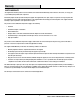
Warranty LIMITED WARRANTY The supplier warrants this product to be free from defects in material and workmanship, under normal use and service, for one (1) year (1 year limited parts) from the date of purchase. All warranty repairs must be pre-authorized by the supplier. The supplier will, at its option, replace or repair free of charge any defective part, which the purchaser shall notify their distributor or the supplier within the warranty period.
Pre-Assembly PLANNING ASSEMBLY Before you begin assembly, locate the instructions and hardware. Compare all parts with the Hardware Included and Package Contents lists. Be sure you have all the parts and can identify them. A helping hand is always good. Assemble your mantel with an adult assistant if possible. Some pieces are heavy and will need to be held by a helper. Assembly time will take approximately 30-60 minutes. Before assembly, use scissors to unwrap the parts from the packaging.
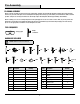
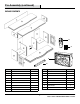
Pre-Assembly (continued) Package Contents N O M P Q Part Description Quantity Part Description Quantity A Top 1 J Shelves 2 B Base 1 K Back Panel 2 C Fixed Shelf 1 L Upper Back Panel 1 D Side Panel 2 M Firebox Brace 1 E Left Interior Panel 1 N Remote Control 1 F Right Interior Panel 1 O Batteries 2 G Upper Side Panel 2 P Firebox Insert 1 H Left Door 1 Q Firebox Trim 1 I Right Door 1 5 HOMEDEPOT.
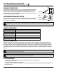
Pre-Assembly (continued) GROUNDING INSTRUCTIONS This heater is for use with 120V power sources. The cord has a three-blade, grounding-type plug. An adapter is available for connecting three-blade grounding-type plugs to two-slot receptacles. The green grounding lug extending from the adapter must be connected to a permanent ground, such as a properly grounded outlet box. The adapter should not be used if a three-slot grounded receptacle is available.
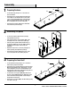
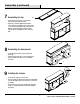
Assembly the base 1 Preparing CC AA □□ Locate the base (B) and place on a soft surface to protect the finish. □□ Insert eight cam lock dowels (AA) into the threaded holes. Make sure the threaded side is facing down so you can insert and tighten each cam lock dowel (AA) into each threaded hole in the top of base (B). Do not overtighten the cam lock dowels (AA). □□ Insert eight wood dowels (CC) into the unthreaded holes into the top of the base (B).
Assembly (continued) AA CC 4 Assembling the fixed shelf AA □□ Turn the fixed shelf (C) upright. □□ With a partner, align the cam lock dowels (AA) with the holes in the top of each panel (D, E, F). It is easier to start at one side and align the holes and wooden dowels (CC) in each panel one at a time. BB □□ Push the fixed shelf (C) until flush with the top of the panels (D, E, F). Insert eight cam locks into the top holes of panels (D, E, F). □□ Tighten the cam locks (BB) by turning clockwise.
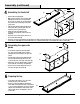
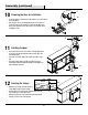
Assembly (continued) 7 Assembling the top AA □□ Locate the top (A) and place on a soft surface, bottom side up, to protect the finish. BB □□ Insert four cam dowels (AA) into the threaded holes. Make sure the threaded side is facing down so you can insert and tighten each cam lock dowel (AA) into each threaded hole in bottom of fixed shelf (C). Do not overtighten the cam lock dowels (AA). 8 Assembling the back panels □□ Locate the upper back panel (L) and lower back panels (K).
Assembly (continued) 10 Preparing the door for installation FF GG □□ Locate the right door (I) and left door (H) and place on a soft surface to protect the finish. □□ Place the open side of each hinge (GG) into the recessed area on each of the right door (I) and left door (H). Insert and tighten two hinge screws (FF) into each of the two holes in each hinge. Do not overtighten screws.
Assembly (continued) 13 Securing the firebox □□ Locate the firebox brace (M) and place it snuggly behind the firebox insert (P) to hold it in position. Do not cover any air venting. PP □□ Insert two large flat head screws (PP) through the holes in the firebox brace (M) and into the base (C). Tighten until secure. M 14 Attaching the anti-tip device to the mantel NN LL KK □□ Push one medium screw (KK) through one washer (LL) and fasten the nylon strap (NN) to the back of the top (A).
Operation 1 Using the remote control 2 Using the manual control □□ To turn the firebox on and off, press the main power switch (5). NOTE: The main power button (5) on the firebox must be turned on for the remote control to function. □□ Press the power button (1) on the control panel (P). The flame effect will turn on. □□ Press the power button (1) on the remote control (N). The flame effect will turn on. □□ Press the flame “+” or flame “–” button (2) to achieve the desired effect (no heat).
Maintenance 1 Removing the access panels 2 Replacing the bulbs NOTE: This fireplace insert uses two clear 120 Volt, 40 Watt, E-12 socket base light bulbs (small base, chandelier candle type bulbs). The light bulbs are located at the bottom of the unit. You can change the light bulbs from the back of the firebox. For convenience, if one of the light bulbs burns out, it may be easier to replace all of the light bulbs at the same time. WARNING: Do not exceed 40 Watts per bulb.
Care and Cleaning IMPORTANT: Always unplug the power cord before cleaning the unit. Do not use any abrasive cleaners on the unit. □□ Any repairs to this appliance should be carried out by qualified/authorized service personnel only. □□ Dust your fireplace mantel regularly with a soft, non-lint producing cloth or household dusting product. □□ Under no circumstances should this appliance be modified.
Service Parts N M P Q Part Description SE Part No. SCH Part No. Part Description SE Part No. SCH Part No. A Top ZZ.2513SE-2.A ZZ.2513SCH.A I Right Door ZZ.2513SE-2.I ZZ.2513SCH.I B Base ZZ.2513SE-2.B ZZ.2513SCH.B J Shelves ZZ.2513SE-2.J ZZ.2513SCH.J C Fixed Shelf ZZ.2513SE-2.C ZZ.2513SCH.C K Back Panel ZZ.2513SE-2.K ZZ.2513SCH.K D Side Panel ZZ.2513SE-2.D ZZ.2513SCH.D L Upper Back Panel ZZ.2513SE-2.L ZZ.2513SCH.L E Left Interior Panel ZZ.2513SE-2.E ZZ.2513SCH.
Questions, problems, missing parts? Before returning to the store, call Home Decorators Collection Customer Service 8 a.m. - 6 p.m., EST, Monday-Friday 1-800-986-3460 HOMEDEPOT.COM/HOMEDECORATORS Retain this manual for future use.
Item Modelo # 1000-050-887 # 658-383 # MTVSC2513SE-2 # MTVSC2513SCH # MFB25WSC-1 Guía de uso y cuidado Colección Silverthorne: CHIMENEA ELÉCTRICA CON REPISA ¿Preguntas, problemas o partes faltantes? Antes de regresar a la tienda, llame al servicio de atención al cliente de Home Decorators Collection 8:00 a.m. a 6 p.m, Hora del Este de lunes a viernes 1-800-986-3460 HOMEDEPOT.
Tabla de Contenidos Tabla de contenidos. . . . . . . . . . . . . . . . . . . . . . . . . . . . . . . . . . . 2 Información de seguridad. . . . . . . . . . . . . . . . . . . . . . . . . . . . . . 2 Garantía. . . . . . . . . . . . . . . . . . . . . . . . . . . . . . . . . . . . . . . . . . . . 3 Pre-ensamblaje. . . . . . . . . . . . . . . . . . . . . . . . . . . . . . . . .
Garantía GARANTÍA LIMITADA El proveedor garantiza que este producto se encuentra libre de defectos en el material y la calidad de ejecución del trabajo, bajo uso y servicio normal por el período de un (1) año (1 año de garantía por las partes) a partir de la fecha de compra. Todas las reparaciones bajo garantía deberán ser previamente aprobadas por el proveedor.
Pre-ensamblaje PLANIFICACION DEL ENSAMBLAJE Antes de iniciar el ensamblaje localice las instrucciones y las piezas. Compare todas las piezas con la lista de piezas incluidas y contenido del embalaje. Asegúrese de tener todas las piezas y de que pueda identificarlas. Siempre es bueno contar con ayuda. Ensámblelo con asistencia de una persona adulta si es posible. Algunas piezas son pesadas y necesitará ayuda. El tiempo de ensamblaje se estima entre 30-60 minutos.
Pre-ensamblaje (continuación) Contenido del paquete N O M P Q Pieza Descripción Cantidad Pieza Descripción Cantidad A Tapa 1 J Estantes 2 B Base 1 K Paneles trasero inferiores 2 C Estante fijo 1 L Panel trasero superior 2 D Paneles laterales 2 M Sujetador de la cámara de combustión 1 E Panel interior izquierdo 1 N Control Remoto 1 F Panel interior derecho 1 O Baterías 2 G Panel lateral superior 2 P Cámara de combustión 1 H Puerta izquierda 1 Q Moldura
Pre-ensamblaje (continuación) INSTRUCCIONES SOBRE LE CONEXIÓN A TIERRA Este calentador se debe usar con 120 voltios. El cable tiene un enchufe como se muestra en la imagen 1A en el diagrama. Hay un adaptador disponible como el que se muestra en 1C para conectar enchufes de tres patas con conexión a tierra en tomas de corriente con dos ranuras.
Ensamblaje 1 Preparación de la base CC AA □□ Localizar la base (B) y colocarla sobre una superficie suave para proteger el acabado. □□ Inserte ocho pasadores de cerradura de leva (AA) dentro de los orificios roscados. Asegúrese de que el lado roscado está mirando hacia abajo de tal manera que pueda introducirlo y ajustar cada uno de los pasadores de cerradura de leva (AA) dentro de cada orificio roscado en la parte superior de la base (B). No apriete en exceso los pasadores de cerradura de leva (AA).
Ensamblaje (continuación) AA CC 4 Ensamblaje del estante fijo AA □□ Coloque el estante fijo (C) en posición vertical. □□ Con la ayuda de alguien, alinee los pasadores de cerradura de leva (AA) con los orificios en la parte superior de cada panel (D, E, F). Es más fácil comenzar por un lado y alinear los orificios y clavijas de madera (CC) en cada panel, uno a la vez. BB □□ Empuje el estante fijo (C) hasta alinearlo con la parte superior de los paneles (D, E, F).
Ensamblaje (continuación) 7 Ensamblaje del tope AA □□ Localice el tope (A) y colóquelo sobre una superficie suave, con la cara inferior hacia arriba, para proteger el acabado. BB □□ Inserte cuatro pasadores de leva (AA) en los orificios roscados. Asegúrese de que el lado roscado está mirando hacia abajo de tal manera que pueda introducirlo y ajustar cada uno de los pasadores de cerradura de leva (AA) dentro de cada orificio roscado en la parte inferior del estante fijo (C).
Ensamblaje (continuación) 10 Preparación de la puerta para su instalación FF GG □□ Localice la puerta derecha (I) y la puerta izquierda (H) y colóquelas sobre una superficie suave para proteger el acabado. □□ Coloque el lado abierto de cada bisagra (GG) en la parte empotrada de la puerta derecha (I) y puerta izquierda (H). Inserte y apriete dos tornillos de bisagras (FF) en cada uno de los dos orificios en cada bisagra. No apriete en exceso los tornillos.
Ensamblaje (continuación) 13 Fijar la cámara de combustión □□ Localice el sujetador de la sección de la cámara de combustión (M) y colóquelo ajustado detrás de la cámara de combustión (P) para mantenerla en su lugar. No cubra ninguna abertura de ventilación. PP □□ Inserte dos tornillos de cabeza plana (PP) a través de los orificios en el sujetador de la cámara de combustión (M) y en la base (C). Apriete hasta fijarlos.
Operación 1 Uso del control remoto 2 Uso del control manual □□ Para encender y apagar la cámara de combustión, pulse el interruptor de alimentación principal (5). NOTA: El botón de alimentación principal (5) en la cámara de combustión debe estar encendido para que el control remoto funcione. □□ Pulse el botón de encendido (1) en el panel de control (P). El efecto de llama se encenderá. □□ Pulse el botón de encendido (1) en el control remoto (N). El efecto de llama se encenderá.
Mantenimiento 1 Desmontaje de los paneles de acceso 2 Reemplazo de las bombillas NOTA: Esta chimenea utiliza dos bombillas transparentes de 120 voltios, 40 vatios para zócalo E-12 (base pequeña, bombillas tipo vela para lámparas tipo araña). Las bombillas están ubicadas en la parte inferior de la unidad. Puede cambiar las bombillas desde la parte trasera de la cámara de combustión. Para su conveniencia, si una de las bombillas se quema, quizás sea más fácil sustituir todas las bombillas a la vez.
Cuidado y limpieza IMPORTANTE: Siempre desenchufe el cable de alimentación antes de limpiar la unidad. No utilice ningún limpiador abrasivo en la unidad. □□ Cualquier reparación de la unidad debe ser llevada a cabo sólo por personal calificado/autorizado. □□ Limpie regularmente la repisa de su chimenea con un paño suave sin pelusas o un producto casero para quitar el polvo. □□ Bajo ninguna circunstancia este electrodoméstico debe ser modificado.
Piezas de repuestos N M P Q Pieza Descripción SE Número de pieza SCH Número de pieza Pieza Descripción SE Número de pieza SCH Número de pieza A Tapa ZZ.2513SE-2.A ZZ.2513SCH.A H Puerta izquierda ZZ.2513SE-2.H ZZ.2513SCH.H B Base ZZ.2513SE-2.B ZZ.2513SCH.B I Puerta derecha ZZ.2513SE-2.I ZZ.2513SCH.I C Estante fijo ZZ.2513SE-2.C ZZ.2513SCH.C J Estantes ZZ.2513SE-2.J ZZ.2513SCH.J D Paneles laterales ZZ.2513SE-2.D ZZ.2513SCH.D K Paneles trasero inferiores ZZ.2513SE-2.K ZZ.
¿Preguntas, problemas o partes faltantes? Antes de regresar a la tienda, llame al servicio de atención al cliente de Home Decorators Collection 8:00 a.m. a 6 p.m, Hora del Este de lunes a viernes 1-800-986-3460 HOMEDEPOT.COM/HOMEDECORATORS Guarde este manual para futuras referencias.