Item #1008 622 049 1008 622 432 Model #N608-BN N608-CB 1008 622 051 1008 622 431 N608-MBK N608-MWH USE AND CARE GUIDE 72 IN KENSGROVE II INDOOR/COVERED OUTDOOR CEILING FAN Questions, problems, missing parts? Before returning to the store, call Hubspace Customer Service 8 a.m. - 7 p.m., EST, Monday-Friday, 9 a.m. - 6 p.m., EST, Saturday 1-877-592-5233 HOMEDEPOT.COM/HUBSPACE Visual instruction of how to install this fan: Visit www.homedepot.
Table of Contents Table of Contents . . . . . . . . . . . . . . . . . . . . . . . . . . . . . . . . . . 2 Safety Information . . . . . . . . . . . . . . . . . . . . . . . . . . . . . . . . . 2 Warranty . . . . . . . . . . . . . . . . . . . . . . . . . . . . . . . . . . . . . . . . . 3 Pre-installation . . . . . . . . . . . . . . . . . . . . . . . . . . . . . . . . . . . . 3 Installation . . . . . . . . . . . . . . . . . . . . . . . . . . . . . . . . . . . . . . . 6 Assembly . . . . . . . . . . . . . . . .
Warranty The manufacturer warrants the fan motor to be free from defects in workmanship and material present at time of shipment from the factory for a period of lifetime after the date of purchase by the original purchaser. The manufacturer warrants the light kit (excluding any glass), to be free from defects in workmanship and material present at time of shipment from the factory for a period of five years after the date of purchase by the original purchaser.
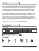
Pre-Installation (continued) HARDWARE INCLUDED NOTE: Hardware not shown to actual size. AA BB CC DD EE Part Description Quantity AA Plastic wire nut 3 BB Blade attachment screw and fiber washer 25 CC 1.
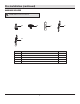
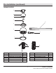
Pre-Installation (continued) PACKAGE CONTENTS A B C D G E F H I ALL ON / OFF J ON / OFF 6 SPEED BRIGHTNESS BREEZE COLOR TEMP. 2HR 4HR K 8HR TIMER SUMMER WINTER FAN DIRECTION HOLD 3 SEC.
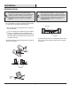
Installation MOUNTING OPTIONS WARNING: To reduce the risk of fire, electric shock, or personal injury, mount the fan to an outlet box marked acceptable for fan support using the screws provided with the outlet box. An outlet box commonly used for the support of lighting fixtures may not be acceptable for fan support and may need to be replaced. If in doubt, consult a qualified electrician. NOTE: You may need a longer downrod to maintain proper blade clearance when installing on a steep, sloped ceiling.
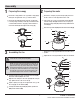
Assembly 1 2 Preparing the motor Preparing the canopy Remove the canopy bottom cover (C) from the canopy (B) by turning the canopy bottom cover (C) counterclockwise. Remove the cotter pin (GG) and clevis pin (HH), and loosen the two collar set screws (II) from the motor collar. Remove the mounting bracket (A) from the canopy (B) by loosening canopy mounting screws (FF) a half turn from the screw head. Next, turn the canopy (B) counterclockwise to remove the mounting bracket (A) from the canopy (B).
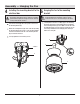
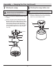
Assembly — Hanging the Fan 4 5 Installing the mounting bracket to the electrical box Hanging the fan to the mounting bracket WARNING: The tab in the ring must rest in the groove of the hanger ball/downrod assembly (D). Failure to properly seat the tab in the groove could cause damage to the wiring.
Assembly — Hanging the Fan (continued) 6 Making the electrical connections White WARNING: Check to see that all connections are tight, including ground, and that no bare wire is visible at the wire nuts (except for the ground wire). CAUTION: To reduce the risk of electric shock, this fan must be installed with an isolating wall control/switch. Ground conductor Black Outlet Box A NOTE: The fan must be installed at a maximum distance of 20 ft.
Assembly — Hanging the Fan (continued) 7 Attaching the canopy 8 NOTE: Adjust the canopy mounting screws (FF) as necessary until the canopy (B) and canopy bottom cover (C) are snug. WARNING: Make sure the tab on the mounting bracket (A) properly sits in the groove in the hanger ball (KK) before attaching the canopy (B) to the mounting bracket (A) by turning the canopy housing until it drops into place.
Assembly — Attaching the Fan Blades 9 Attaching the blades to the blade arms Attach the blades (G) to the blade arms (H) using the three blade attachment screws and fiber washers (BB). Insert a blade attachment screws and fiber washers (BB) into the blade arm (H), but do not tighten. BB G Repeat for the two remaining screws and fiber washers (BB). Tighten each screw securely starting with the center screw. Make sure the blade (G) is straight. H Repeat these steps for the remaining blades.
Assembly — Installing the Light Kit 11 Installing the LED light kit to the light kit mounting plate CAUTION: Before starting installation, disconnect the power by turning off the circuit breaker or removing the fuse at the fuse box. Turning power off using the fan switch is not sufficient to prevent electric shock.
Operation SETTING UP THE TRANSMITTER NOTE: The remote has been pre-paired in the factory for your convenience. NOTE: Batteries will weaken with age and should be replaced before leaking takes place as this will damage the remote control. Dispose of used batteries properly and keep them out of the reach of children. 1+ LEARN K 0 Remove the battery cover by pressing firmly on the arrow and sliding the cover off. CC Install two 1.5V AAA batteries (CC) (included).
Operation (continued) OPERATING YOUR FAN AND REMOTE CONTROL NOTE: The fan will store the last used speed setting for the next time it is turned on. NOTE: On each start up of your ceiling fan, the fan blades will oscillate back and forth. This is a NORMAL OPERATION for DC motor ceiling fans as they go through a calibration cycle. The fan is NOT DEFECTIVE. Power ALL button: Press and release the power button to turn the fan and light on or off.
Operation (continued) BBB INSTALLING THE REMOTE CONTROL HOLDER AAA XX YY ZZ To install the remote control bracket (XX), remove the two screws holding the switch cover plate (YY). Do not remove the cover plate (YY). Orient the bracket (XX) by lining up the two mounting holes with those on the cover plate (YY). Insert and tighten the screws (ZZ).
Care and Cleaning Do Check the support connections, brackets, and blade attachments twice a year. Make sure they are secure. Because of the fan’s natural movement, some connections may become loose over time. It is not necessary to remove the fan from the ceiling. Clean your fan periodically. Use only a soft brush or lint-free cloth to avoid scratching the finish. The plating is sealed with a lacquer to minimize discoloration or tarnishing.
Application Set-Up NOTE: For more information on smart remote set up, please refer to the quick start guide located in the remote pack. NOTE: To use Alexa to change the white temperature of the light, please make sure the light is turned on first. Questions, problems missing parts? Please call Hubspace Customer service 8 a.m. - 7 p.m. EST, Monday - Friday; 9 a.m. - 6 p.m.
Voice Commands The Kensgrove II 72 in. LED Indoor Smart Color Changing Ceiling Fan works with Alexa and Google Assistant. This section lists some of the voice commands you can use. To view these and other commands, go to http://hubspaceconnect.com/. Google Alexa When you want to... Ask Alexa to... When you want to... Ask Google to... Turn on the fan only. … turn on fan power. Turn on the fan only. … turn on fan power. Turn off the fan only.
Troubleshooting (HubspaceTM) Problem Solution My hubspace device is not connecting to Wi-Fi. Make sure your device is connected to a power source. Your Internet connection or Wi-Fi network may be down. My device cannot find any Wi-Fi networks. Make sure you have a 2.4GHz capable Wi-Fi network within range of the device you are trying to add. My device is in a location that does not have Wi-Fi. Can I still use it with the Hubspace app? Yes: Use the app on a phone with an Internet connection like LTE.
This device complies with part 15 of the FCC Rules. Operation is subject to the following two conditions: (1) This device may not cause harmful interference, and (2) this device must accept any interference received, including interference that may cause undesired operation. WARNING: Changes or modifications to this unit not expressly approved by the party responsible for compliance could void the user's authority to operate the equipment.