CSST Flexible Gas Pipe System Design and Installation Manual
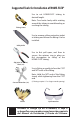
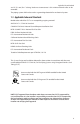
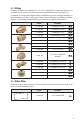
Suggested Tools for Installation of HOME-FLEX® Use to cut HOME-FLEX® tubing to desired length. Tubing Cutter Note: Turn knob slowly while rotating around the tubing to avoid bending or crushing the tubing. Use to remove yellow protective jacket at tubing end where the fitting is to be installed. Utility Knife Use to first pull open, and then to secure, the retainer ring in place on first corrugation (or valley) of the HOME-FLEX® tubing.
Table of Contents Chapter 1: Introduction 1.1 User Warnings . . . . . . . . . . . . . . . . . . . . . . . . . . . . . . . . . . . . . . . . . . . . . . . . . . . . . . . . . 1 1.2 Limitations of Manual . . . . . . . . . . . . . . . . . . . . . . . . . . . . . . . . . . . . . . . . . . . . . . . . . . 2 1.3 Applicable Codes and Standards . . . . . . . . . . . . . . . . . . . . . . . . . . . . . . . . . . . . . . . . 3 Chapter 2: Description of System Components 2.1 Tubing . . . . . . . . . . . . . . . . .
.5 Meter connections . . . . . . . . . . . . . . . . . . . . . . . . . . . . . . . . . . . . . . . . . . . . . . . . . . . . 25 Connection by Special Termination Fitting . . . . . . . . . . . . . . . . . . . . . . . . . . 26 Direct Connection . . . . . . . . . . . . . . . . . . . . . . . . . . . . . . . . . . . . . . . . . . . . . . . . . 26 4.6 Appliance connections . . . . . . . . . . . . . . . . . . . . . . . . . . . . . . . . . . . . . . . . . . . . . . . .
Chapter 1: Introduction 1.1 User Warnings HOME-FLEX® Corrugated Stainless Steel Tubing (CSST) flexible gas piping material must be installed by a Qualified Installer who has been certified in the use of the HOME-FLEX® or VPC Alpha-FLEX™ gas piping systems.
Introduction 1.2 Limitations of Manual This System Design and Installation Manual is intended to assist the professional gas pipe installer in the design, installation, and testing of the HOME-FLEX® flexible gas piping system for residential, commercial, and industrial buildings. It is not possible for this guide to anticipate every variation in construction style, building configuration, appliance requirement, or local restriction. This document will not cover every application.
Applicable Codes and Standards and 2" (51 mm) for 1" tubing. Under no circumstances is this minimum bend radius to be exceeded. The piping system shall not be used as a grounding electrode for an electrical system. 1.3 Applicable Codes and Standards Model codes which list CSST as an acceptable gas piping material: ANSI/IAS LC-1 / CSA 6.26 Standard CANADA-CSA B149.1 Natural Gas and Propane Installation Code NFPA 54/ANSI Z 223.
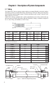
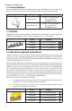
Chapter 2: Description of System Components 2.1 Tubing The HOME-FLEX® fuel gas piping system employs corrugated, flexible, semi-rigid stainless steel tubing with brass attachment fittings terminating in NPT pipe fittings for integration into traditional rigid black pipe systems or direct connection to gas systems. Tubing is available in sizes of ½", ¾", and 1". HOME-FLEX® tubing is jacketed with a yellow polyethylene cover clearly marked with gas pressure rating, and EHD* (Equivalent Hydraulic Diameter).
2.2 Fittings HOME-FLEX® fittings are available for ½", ¾", and 1" HOME-FLEX® tubing and allow for easy connection to gas systems and accessories using standard NPT threads. (See Figure 2.1) In addition to standard NPT adapter fittings, the following are also available: Tee fittings to accommodate branch lines in tubing runs, reducer tees to integrate with different sized tubing runs, and special termination flanges for convenient gas appliance connections. Part No.
Description of System Components 2.4 Pressure Regulators Pressure regulators are used in elevated pressure system installations (over 14 inches water column, or ½ PSI) to reduce pressure to standard low pressure required for appliances. Part No. Description Maxitrol 325-3L ½" NPT 7-11" w.c. Gas Line Pressure Regulator (250,000 Btu/hr max) Maxitrol 325-5AL ¾" NPT 7-11" w.c. Gas Line Pressure Regulator (425,000 Btu/hr max) 2.
Bonding Clamps Quick-connect devices provide a safe and easy way to make connections to moveable outdoor gas appliances like barbecues and space heaters. Quick-connect devices used with HOME-FLEX® gas piping systems must conform to ANSI Z21.15, CGA 9.1, 9.2, 6.9 and AGA/ CGA 7-90/CR94-001. A shut-off valve should be installed upstream of the quick-connect device and remain in the off position when the quick-connect device is not in use. All installations and devices must conform with local codes.
Description of System Components 2.10 Replacement Parts HOME-FLEX® fittings require a retainer ring, a non-metallic gasket, and an o-ring for proper assembly (see Figure 2.1 on page 4). Should any of these components be damaged or misplaced, packs of replacement rings are available. Part No.
Chapter 3: Sizing and Configurations 3.1 Configuration Before routing HOME-FLEX® tubing, it is advisable to prepare a sketch from the building plans showing the locations of appliances to be serviced by the gas line, the load demands of each appliance, the point of delivery (location of gas meter or second stage liquid petroleum (LP) regulator), system pressure, and possible piping routes and lengths.
• For natural gas with a specific gravity of 0.60, one cubic foot per hour (1 CFH) is approximately 1,000 BTUH. • For LP gas with a specific gravity of 1.52, one cubic foot per hour (1 CFH) is approximately 2,500 BTUH. For any given system and its load requirements, there are several piping system designs available to the installer using HOME-FLEX® tubing. The sections below will outline several demand scenarios and the different system options open to the installer.
Sizing Methods and Examples routed to each appliance location. Manifold stations are located as close as possible to the appliance(s) with the greatest load. Parallel layouts are most commonly used in ¼ to ½ PSI systems. Dual Pressure Systems Elevated pressure systems generally have a main line from the gas supply to one or more gas pressure regulators and then a manifold with "home runs" to appliances. These runs may branch off through use of a tee, if gas loads permit.
Sizing and Configurations inlet pressure (recommended 5 inches w.c. for natural gas and 10.5 inches w.c. for natural gas) from the gas source pressure (gas meter for natural gas or the secondary regulator for LP). Low pressure series systems are sized using the "longest length method" (also known as the "branch length method") in the same manner as low pressure black steel pipe systems. Tables from the National Fuel Gas Code (NFPA 54) are used to calculate the sizing.
Sizing Methods and Examples Step 2 Size Section B: Determine the length of the run from the meter to the range oven and the load delivered. • The length from the meter to the range oven is 20 feet (A + B), and the load is 40 CFH (40,000 BTUH divided by 1000 CF per BTU). • Consulting Table 7.1, we see that for a 20-foot run, ½" tubing will supply up to 51 CFH. The correct size tubing for section B is ½".
Sizing and Configurations Step 4 Size Section D: Determine the length from the meter to the water heater. • A + D = 32 feet, and the load of the water heater is 25,000 BTUH = 25 CFH. • Table 7.4 shows that ½" tubing has a total load capacity of 116 CFH at 40 feet, so ½" tubing is the correct size. Step 5 Size Section E: Determine the length from the Range oven to the Furnace. • A + E= 30 feet and the load of the furnace is 40,000 BTUH = 40 CFH. • Table 7.
Sizing Methods and Examples Example 4: Medium Pressure Parallel Arrangement with a Series Branch This installation has a barbecue installed near the water heater. Given the number of appliances, a parallel arrangement was selected for the system, with a single run supplying the barbecue and the water heater in series. Med Pressure (12-14" w.c.) 1/2 PSI Gas Meter 30,000 BTUH Dryer Range Oven 40,000 BTUH D Furnace C B 60,000 BTUH E A BBQ F 50,000 BTUH Water Heater G 25,000 BTUH Figure 3.
Sizing and Configurations Step 6 Size Section F: Determine the total length and load. • The BBQ load is 50 CFH and the length is 60 feet (A + E + F). • ½" Tubing has a maximum capacity of 96 CFH at 60 feet so ½" is the correct size. Step 7 Size Section G: Determine the total length and load. • The water heater load is 25 CFH and the length is 50 feet (A + E + G). • ½" Tubing has a maximum capacity of 104 CFH at 50 feet, so ½" is the correct size.
Sizing Methods and Examples 400 CFH, which at 70 feet can be supplied by 1¼" pipe with a maximum capacity of 490 CFH. 1¼" pipe is the correct size for section A2. • To size section A3, we can reduce the load by another 190 CFH to 210 CFH for the remaining heater and the water heater. At 70-feet, 1" pipe can supply a maximum of 240 CFH, which is sufficient for the run. 1" pipe is the correct size. • To size section A4, the load is reduced to just the 60 CFH of the water heater.
Chapter 4: Installation Practices 4.1 General Practices HOME-FLEX® CSST flexible gas piping material must be installed by a Qualified Installer who has been certified in the use of the HOME-FLEX® or VPC Alpha-FLEX™ gas piping systems. Installers must meet applicable qualifications set forth by the state and/or local administrative authorities which enforce the plumbing, mechanical, electrical and/or building codes at the locale where the gas piping is to be installed.
Fitting Assembly Table 4.2 Recommended Horizontal and Vertical Support Spacing for HOME-FLEX® Tubing Tubing Size Horizontal Support Spacing ½" (13 mm) 6 ft. ¾" (19 mm) 1" (25 mm) 8 ft. (USA) 6 ft. (CAN) Vertical Support Spacing 10 ft. should not be supported by conductive metallic systems such as metallic appliance vents, ducting, or piping. Electrical cables must be avoided and cannot be used as supports.
Installation Practices Step 4 Place retainer ring on HOME-FLEX® tubing Pulling with two pliers, stretch the brass retainer ring open so that it can be easily placed in the first valley of the tubing (inset). Being careful to not dent the tubing, clamp the ring in place by applying gentle pressure 360° around the ring. It should fit tightly and not easily spin around the tubing. Step 5 Install HOME-FLEX® fitting in destination (manifold, pipe system, fixed appliance, etc.
Routing assembly, wrap with the assembly with self-bonding silicone tape from the tubing jacket to the end of the nut flange. 4.3 Routing General Routing Practices Routing requirements for CSST flexible gas pipe can vary by locality. Be sure to confirm the requirements of the administrative authority for the location where HOME-FLEX® is to be installed before installing HOME-FLEX®. In general, HOME-FLEX® can be routed: • Beneath, through, and along side floor and ceiling joists.
Installation Practices Holes and Cuts in Top and Sole Plates Holes bored through top plates, top frame members and sole plates should not exceed 50% of the width of the structure, and should be in the center of the structure. If a sole or plate is to be cut for the routing of HOME-FLEX® tubing, the width of the cut should be ½" greater than the outside diameter of the tubing and no greater than 2 inches. Tubing must be protected with striker plates in accordance with Section 4.4. (See Figure 4.
Routing NOTE: Manifold stations which are composed of multiport manifold(s), shut off valve, and pressure regulator shall not be installed in concealed locations regardless of the qualifications of tubing fittings. New Installations HOME-FLEX® can be connected to steel piping systems through threaded pipe connections. This can be a sub-out run to an appliance connection, be outdoors to a meter, etc.
Installation Practices ½" larger than the outer diameter (OD) of the CSST tubing. Fittings and joints are not permissible in such runs—the run must be one unbroken line of tubing. Runs underneath slabs must be sleeved and vented per local codes. (See Figure 4.8 and Figure 4.9) Note: If installed underneath mobile homes or in crawl spaces, HOME-FLEX® should be installed in accordance with the above Outdoor Installation Issues section.
Meter connections 5. If striker plates can’t reasonably be installed (like between floors with enclosed joist areas or installations when walls are already in place), schedTypical Wall Stud Typical Wall Stud ule 40 steel pipe has been found acceptable by CSA In(Wood or Metal) (Wood or Metal) 1 33-1/2" ⁄2" ternational for puncture protection.
Installation Practices is not supported independent of the building structure or gas piping system, HOME-FLEX® tubing cannot be used to connect directly to the meter. Connection by Special Termination Fitting Do not use HOME-FLEX® CSST as a direct connection if the meter must be supported by the piping system.
Appliance connections can be made with rigid pipe connected to the main HOME-FLEX® system. The rigid stub-out must be fastened to the wall or floor using a pipe flange or other rigid mounting object. Connections made between HOME-FLEX® and moveable appliances must be made with a HOME-FLEX® Flexible Appliance Connector, or similar approved device. Direct connections between HOME-FLEX® CSST and moveable appliances are not allowed.
Installation Practices Outdoor Appliances: Barbecue Grills, Gaslights, and Heaters Channel Non-metallic Block Roof Figure 4.19 Non-movable outdoor appliances, such as fixed barbecues, gas lights, or heaters can be directly connected with HOME-FLEX® so long as such connections are permissible by local code. On a deck, the outdoor portion of the tubing run must be supported against the sides of joists.
Manifold Stations routed through a non-metallic sleeve appropriate for the application. Sleeves are not required for routing through ceramic liner in heat generating fireplaces. Spaces between the jacket and penetration at interior and/or exterior locations can be caulked. The jacket can be removed inside the firebox. Attachment to the HOME-FLEX® system is usually made at the fireplace shut-off valve, often located in the control area beneath the burner unit or at the side of the log set.
Installation Practices 4.8 Pressure Regulators Installation Requirements A HOME-FLEX® gas piping system used with inlet gas pressures in excess of ½ PSI, but servicing appliances rated for a maximum of ½ PSI, must contain a pounds-to-inches regulator to limit the downstream pressure to no more than ½ PSI. Gas pressure regulators must comply with a nationally recognized standard for pressure regulators such as ANSI Z21.80/CSA 6.22.
Underground Installations Gas line regulators do not vent gas under normal operating conditions. A regulator that is venting gas should be replaced immediately. Performance Testing A performance test of the regulator should be conducted to confirm that adequate pressure reaches all appliances. During the test, all appliances should be running at full load to make sure that adequate pressure is maintained under full-load conditions for the gas piping system.
Installation Practices HOME-FLEX® is installed. Electrical work must be performed by a qualified person recognized by the local jurisdictional authority as being capable of performing such work. All installations of CSST for use in natural and propane (LP) gas piping systems in single and multi-family structures, whether or not the connected gas equipment is electrically powered, require direct bonding.
Chapter 5: Inspection, Repair, and Replacement of CSST 5.1 Minimum Inspection Requirements Checklist All installations shall be inspected by the authority having jurisdiction in accordance with state and local mechanical, electric, and/or plumbing codes, or in the absence of such codes, the National Fuel Gas Code (NFPA 54/ANSI Z 223.1), the International Fuel Gas Code (IFGC), the National Electric Code (NFPA 70), and/or the Uniform Plumbing Code (UPC), as applicable.
Inspection, Repair, and Replacement of CSST 5.2 Repair of Damaged Tubing If tubing is damaged before, during, or after installation, refer to these guidelines to determine the proper course of repair. Less than 1/2 D When Pipe Needs to be Replaced If the tubing is only slightly dented due to impact, it may not need to be replaced. A slight dent is defined as a dent less than 1/3 the diameter of the pipe and does not require replacement. (Figure 5.1) D Figure 5.
Chapter 6: Pressure Test Procedures The final installation must be inspected and tested for leaks in accordance with local and/ or state codes. In the absence of local guidelines, test the system at 1½ times the maximum working pressure, but not less than 3 PSI, using the procedures specified in Chapter 8 "Inspection, Testing and Purging" of the National Fuel Gas Code (NFPA 54/ANSI Z223). When local codes are more stringent, local codes must be followed.
Pressure Test Procedures 6.3 Appliance Connection Check Procedure After the final pressure test, inspection, and final construction are complete, appliances may be connected to the HOME-FLEX® gas piping system. This final connection can be accomplished by a HOME-FLEX® Appliance Connector (or similar device), direct connection with CSST tubing, or with rigid black pipe, depending on the appliance (see Section 4.6 for installation details and guidelines).
Chapter 7: Sizing/Capacity Tables Natural Gas Sizing Tables Table 7.1 Low Pressure (6 - 7 in w.c. with 0.5 in drop) . . . . . . . . . . . . . . . . . . . . . . . . . . 38 Table 7.2 Low Pressure (6 - 7 in w.c. with 1 in drop) . . . . . . . . . . . . . . . . . . . . . . . . . . . 38 Table 7.3 Regulator Outlet (8 - 10 in w.c. with 3 in drop) . . . . . . . . . . . . . . . . . . . . . . . 39 Table 7.4 Medium Pressure (12 - 14 in w.c. with 6 in drop) . . . . . . . . . . . . . . . . . . . . . . 39 Table 7.
38 EHD 18 25 31 EHD 18 25 31 Tube Size ½" ¾" 1" Tube Size ½" ¾" 1" 71 10 59 15 51 20 46 25 42 30 37 40 89 33 50 82 30 60 76 28 70 73 27 75 71 26 80 67 25 90 63 24 100 57 21 125 93 52 19 150 79 45 17 200 63 37 14 300 54 32 12 400 47 28 11 500 95 10 79 15 69 20 62 25 57 30 50 40 45 50 41 60 38 70 37 75 36 80 96 34 90 91 32 100 81 29 125 74 27 150 64 23 200 925 627 500 426 376 339 289 255 230 211 203 196 183 173 1
Table 7.3 Regulator Outlet (8 - 10 in w.c. with 3 in drop) 69 60 64 70 62 75 80 90 100 125 150 200 300 400 500 60 57 54 49 45 39 Table 7.4 Medium Pressure (12 - 14 in w.c.
40 70 75 80 90 100 125 150 200 300 400 500 75 65 58 25 30 40 50 60 70 75 80 90 100 125 150 200 300 400 500 31 11881 8228 6637 5698 5063 4596 3946 3506 3183 2934 2828 2733 2568 2428 2157 1959 1682 1357 1165 1035 20 1" 15 25 3855 2783 2300 2009 1809 1661 1451 1306 1199 1115 1080 1047 991 943 849 779 681 563 492 443 10 ¾" 5 Tubing Length (ft) Maximum Capacity of HOME-FLEX® CSST in Cubic Feet per Hour (CFH) of Natural Gas (Approximate 1000 BTU per cubic foot) Minimum Gas Pr
Table 7.7 Propane Low Pressure (11 in w.c. with 0.5 in drop) 150 200 300 400 500 42 41 39 37 82 30 71 26 58 22 85 50 19 75 45 17 10 15 20 25 30 40 50 60 322 232 192 168 151 139 121 109 100 5 93 70 90 75 Tubing Length (ft) 87 80 83 90 79 100 71 125 65 150 57 200 47 300 41 400 37 500 Maximum Capacity of HOME-FLEX® CSST in Cubic Feet per Hour (CFH) of House Propane Gas (Approximate 2520 BTU per cubic foot) Minimum Gas Pressure: 13 - 14 in w.c.
42 70 75 80 90 100 125 150 200 300 400 500 Table 7.10 Propane Elevated Pressure (5 PSI with 3.
43 95 175 360 680 1400 2100 3950 6300 11000 23000 3/8" ½" ¾" 1" 1¼" 1½" 2" 2½" 3" 4" 10 ¼" Tube Size 15800 7700 4350 2750 1460 950 465 250 120 65 29 20 12800 6250 3520 2200 1180 770 375 200 97 52 24 30 10900 5300 3000 1900 990 660 320 170 82 45 20 40 9700 4750 2650 1680 900 580 285 151 73 40 18 50 8800 4300 2400 1520 810 530 260 138 66 36 16 60 8100 3900 2250 1400 750 490 240 125 61 33 15 70 7500 3700 2050 130
Chapter 8: Definitions A.G.A. American Gas Association ANSI Z223.1 1988 The 1988 edition of the National Fuel Gas Code published by American National Standard Institute. Also known as NFPA 54 (National Fire Protection Association). Appliance (Equipment) Any device which utilizes natural gas or propane as a fuel or raw material to produce light, heat, power, refrigeration or air conditioning. Approved Acceptable to the authorities having jurisdiction.
PSI Pounds per square inch gauge. The pressure, as read from a measurement gage or device. Gauge pressure is pressure above atmospheric pressure. Purge To displace the original air, or gas, or a mixture of gas and air in a gas conduit with a new air/gas mixture. Regulator A device that reduces and controls pressure. It automatically opens and closes in response to changing pressure conditions in the downstream piping.
Please PRINT Your Name Here I, ___________________________, have read the HOME-FLEX® System Design and DD YY Installation Manual and understand the installation requirements of the HOME-FLEX® CSST system. I am a Qualified Installer of gas plumbing per the governing local authority at the location where HOME-FLEX® is to be installed, and am aware of all local plumbing and/or building codes applicable to this location.
HOME-FLEX® certification can be completed online at: homeflex.