
Installation Guide


27
Appliance connections
can be made with rigid pipe connected to the main HOME-FLEX® system. The rigid stub-out
must be fastened to the wall or oor using a pipe ange or other rigid mounting object.
Connections made between HOME-FLEX® and moveable appliances must be made with a
HOME-FLEX® Flexible Appliance Connector, or similar approved device.
Direct connections between HOME-FLEX® CSST and moveable appliances are not allowed.
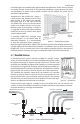
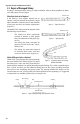
Direct Connection
In most localities, xed appliances may be directly
connected to HOME-FLEX® exible gas piping sys-
tems. When located in a secure dedicated place,
like an attic or garage, the gas piping can be con-
nected directly to the appliance shut-o valve
without installing a special termination ange or
exible appliance connector. (Figure 4.17)
Pad-Mounted Equipment
Gas equipment like pool heaters, generators,
heat pumps, and gas air conditioners that are
mounted on concrete pads should connect to
the HOME-FLEX® system at a termination tting
with either black steel pipe or an approved out-
door appliance connector. Direct connection
of HOME-FLEX® to pad-mounted equipment is
allowed when the CSST is securely supported and
protected from physical damage, so long as such
practice is permissible by local and state codes.
Any exposed tubing should be wrapped with
self-bonding silicone tape, sealing the tting con-
nection.
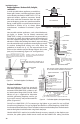
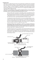
Roof Top Equipment
Special mechanical protec-
tion of HOME-FLEX® tubing is
not required for roof-mount-
ed equipment unless the
tubing may be subject to
physical damage in the loca-
tion. HOME-FLEX® tubing
should penetrate the roof
within 6 feet of the equipment
location, whenever possible.
Long runs of tubing on the
roof should be supported with non-metallic blocks at the intervals specic in Table 4.2, and
raised above the roof at the height dictated by local code. (Figure 4.18)
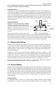
In addition to non-metallic blocks, HOME-FLEX® can be supported with a strut or channel
running from block to block. This provides a secure, damage resistant track for the CSST and
allows for the block spacing to be set at every 8 feet. The channel run should be a ⁄" gal-
vanized shallow channel with splice plates at joints and bends. HOME-FLEX® tubing should
be rmly attached to each block with metallic clamps designed for the strut, or other appro-
priate fastener. Black UV resistant cable ties can be used at intermediate points to ease the
rolling out of HOME-FLEX®. Blocks should be attached to the roof surface in compliance with
the roong manufacturer’s instructions. (Figure 4.19)
Any HOME-FLEX® tubing run vertically up the side of a building must be protected in accor-
dance with "Outdoor Installation Issues" in Section 4.3.
appliance
shut-off valve
drip leg
sediment trap
(if
required by code)
union
(if required by code)
Figure 4.17 Direct Connection to Fixed Appliance
Non-moveable Appliance
Union (if required
by code)
Drip Leg
Sediment Trap
(if required by
code)
Appliance
Shut-off Valve
TYPICAL:
NON-METALLIC TUBING SUPPORT
SPACING PER TABLE 4-2
*TUBING ELEVATED
4-6" TYP. ABOVE ROOF
S
TANDARD ROOF
PENETRATION
TUBING CLIP
CSST
HUNG CEILING
SHUT-OFF VALVE UNION
GAS
APPLIANCE
*HEIGHT OF ELEVATION BASED ON LOCAL PLUMBING/BUILDING
CODE REQUIREMENTS AND/OR WINTER ICE BUILDUP.
Figure 4.18 Roof Top Equipment Installation
CSST
Tubing Clip
Standard Roof
Penetration
Typical: Non-metallic Tubing Support
Spacing per Table 4.2
Tubing Typically Elevated
4-6" Above Roof*
Shut-off Valve
Union
Gas
Appliance
Hung Ceiling
* Height of elevation based on local plumbing/building code requirements
and/or winter ice buildup.