
Installation Guide


9
Chapter 3: Sizing and Congurations
3.1 Conguration
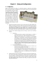
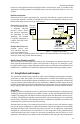
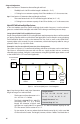
Before routing HOME-FLEX® tubing, it is advisable to prepare a sketch from the building
plans showing the locations of appliances to be serviced by the gas line, the load demands
of each appliance, the point of deliv-
ery (location of gas meter or second
stage liquid petroleum (LP) regulator),
system pressure, and possible piping
routes and lengths. Appliance load
requirements can be obtained from
the manufacturer’s nameplate locat-
ed on the appliance, or provided to
you by the builder or contractor. Per-
forming this sketch will ensure that
you select the proper HOME-FLEX®
tubing and accessories and avoid
potentially costly corrections to the
installation.
a) Determine local piping restrictions prior to purchasing and installing HOME-FLEX®
exible gas tubing. In particular, conrm that the local administrative authority
governing the installation location has accepted the use of Corrugated Stainless
Steel Tubing (CSST) exible gas piping. While CSST is accepted by the major
national and international code bodies, adoption of local codes can lag behind
these bodies, and/or have special requirements in addition to the national codes.
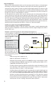
b) Determine the metered (supply) pressure of the gas source at the installation
location.
i) Natural Gas
• Standard low-pressure supply in North America is usually 6-7
inches water column (w.c.), alternatively designated as ¼ PSI.
• Medium pressure supply, such as 14 inches w.c. (½ PSI) provides
signicant CSST size reduction. Check with the local gas utility for
the availability of medium pressure. Most appliances distributed
in the US and Canada are designed to operate up to 14 inches w.c.
• Elevated pressure supply of 2 PSI is typically the highest pressure
supplied within residential buildings in the US and Canada. Instal-
lations for systems of this pressure always require installation of
a pounds-to-inches pressure regulator between the utility meter
and the appliances.
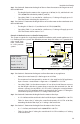
ii) Propane (Liqueed Petroleum or LP) Gas
• The pressure of LP systems are traditionally set to 11 inches w.c. at
the second stage regulator of the system.
• Like natural gas, elevated pressure settings from 14 inches w.c. to
2 and 5 PSI provide CSST size reductions. Check with the gas sup-
plier for availability. For 2 PSI and greater, use a gas line pressure
regulator set to 11 inches w.c. outlet pressure at the appliance
side of the LP system.
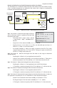
c) Determine the load demand of each appliance to be used at the installation loca-
tion and the total load for all appliances to determine the total capacity needed
for the installation. CFH/BTUH equivalents for natural gas or propane ow can be
obtained from the local gas utility or propane supplier. The capacity tables within
this guide should be used to determine the tubing size required to meet BTUH
input load requirements.