
Installation Guide


12
Sizing and Congurations
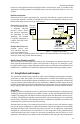
inlet pressure (recommended 5 inches w.c. for natural gas and 10.5 inches w.c. for natural gas)
from the gas source pressure (gas meter for natural gas or the secondary regulator for LP).
Low pressure series systems are sized using the "longest length method" (also known as the
"branch length method") in the same manner as low pressure black steel pipe systems. Tables
from the National Fuel Gas Code (NFPA 54) are used to calculate the sizing. Pressure drop in a
low pressure system is usually limited to ½ inch w.c.
For elevated pressure systems, there are two operating pressures downstream of the gas
source: the pressure set by the service regulator at the meter (usually 2 PSI) which leads to
the pounds-to-inches regulator. The proper drop between the meter and the regulator is usu-
ally 1 PSI, allowing a ¾ PSI regulator drop downstream while providing the ¼ PSI (6-7 inches
w.c.) required for appliances. Between the regulator and the appliances, sizing is calculated
like low pressure systems with the exception that the allowable pressure drop is 3 inches w.c.,
typically sized for one appliance installed as a "home run" from the manifold.
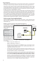
Low Pressure systems (Longest Length/Branch Method)
Sizing of the following systems is done by section. Each section is sized by determining the
total gas load for all appliances and the maximum distance (longest length) over which a
section delivers gas.
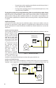
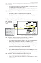
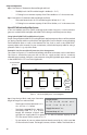
Example 1: Low Pressure System in a Series Arrangement (Figure 3.4)
In this installation, a small number of appliances are located near the natural gas source in
one general area. The short
runs and low appliance load
make it ideal for a series
arrangement.
Step 1 Size Section A: Deter-
mine the longest run from
the source that includes sec-
tion A and the total gas load
it must deliver.
• Meter to range oven is 20 feet (A + B).
• Meter to water heater is 27 feet (A + C).
• Maximum load carried by section A is 65,000 BTUH (range + water heater). Convert
to CFH by dividing by 1000 (for natural gas with a specic gravity of 0.60, 1 CFH =
1,000 BTUH). Maximum load is 65 CFH.
• Find the maximum capacity table that matches the system characteristics, in this
case, natural gas with a minimum gas pressure of 6-7 inches w.c. and a pressure
drop of 0.5 inches w.c. Table 7.1 is the correct table.
• Find the column in the length row that is greater than or equal to the longest run
in the system. The longest run in this system is 27 feet and the table has columns
for 25 and 30 feet. Never round down when sizing. The correct column is 30 feet.
• We then scan down the 30 feet column searching for a CFH value that is greater
than or equal to the total load of the system. At 30 feet, ½" tubing has a maximum
load of 42 CFH so it is not suitable for this system. The next size is ¾" with a maxi-
mum load of 116 CFH. ¾" tubing is the correct size for section A.
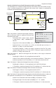
Gas
Meter
Water
Heater
25,000 BTUH
Range Oven
40,000 BTUH
Low Pressure
(5 - 7" w.c.)
A
B
C
Figure 3.4 Low Pressure System—Series Arrangement
Length of Runs:
A = 12' B = 8' C = 15'
Supply Pressure: 6" w.c.
Pressure Drop: 0.5" w.c.