
Installation Guide


22
Installation Practices
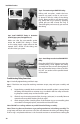
Holes and Cuts in Top and Sole Plates
Holes bored through top plates, top frame mem-
bers and sole plates should not exceed 50% of
the width of the structure, and should be in the
center of the structure. If a sole or plate is to be
cut for the routing of HOME-FLEX® tubing, the
width of the cut should be ½" greater than the
outside diameter of the tubing and no greater
than 2 inches. Tubing must be protected with
striker plates in accordance with Section 4.4. (See
Figure 4.3)
Routing through vertical wall framing
Requirements for boring through vertical mem-
bers of wall framing dier depending on whether
the member is bearing or not. For non-bearing
members (Figure 4.4), the size of the hole should be no larger than 60% of the width of the
member. For bearing members, the size of such hole should be no more than 40% of the
member. (Figure 4.5)
Routing through metallic surfaces
When installing HOME-FLEX® through galvanized steel studs, plastic grommets (often sup-
plied by the stud manufacturer) should be used to reduce potential damage to the yellow
jacket of the HOME-FLEX® tubing. When installing through holes in other metallic members,
the tubing must be similarly protected from contact with the member to prevent mechani-
cal wear on the yellow jacket and tubing. Acceptable means of protection include: rubber
grommets, bushings, HOME-FLEX® Flexible Protective Conduit, PVC tape, thermal contraction
sleeve material, or a minimum of four wraps of 10 mil duct tape.
Concealed Locations for Fittings
The HOME-FLEX® mechanical attachment ttings have been tested and are listed per the
requirements of ANSI LC1 and CSA 6.26 Standard (USA and Canada). This specication pro-
vides test requirements which certify ttings for concealed installations and connections to
appliances where concealing the ttings is the only practical alternative
These guidelines address some of the known situations which may require the use of a con-
cealed tting. While accessibility of ttings is always preferred, there are some situations
where concealing the ttings is the only practical option. This guide cannot address all appli-
cations of concealed ttings, but instead provides general instructions to demonstrate the
principles which apply to ttings listed for installation in concealed locations (National Fuel
Gas Code, NFPA 54 Chapter 7).
Figure 4.3 Holes and Cuts in Top and Sole Plates
2x4
2x4
Stud
Top Plate
Sole Plate
2” Max.
Cut Width
W
Hole for Tubing
W/2 Max
W/2
W/2
Figure 4.4 Holes in Non-Bearing Walls
2x4
Holes up to 60%
of Stud Width
Non-bearing Wall
2
1
⁄8"
Max
3
1
⁄2"
1
1
⁄2"
5
⁄8"
Max
Figure 4.5 Holes in Bearing Walls
2x4
Non-bearing Wall
Holes up to 40%
of Stud Width
1
3
⁄8"
Max
3
1
⁄2"
1
1
⁄2"
1"
Max