
Installation Guide


11
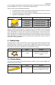
• For natural gas with a specic gravity of 0.60, one cubic foot per hour (1
CFH) is approximately 1,000 BTUH.
• For LP gas with a specic gravity of 1.52, one cubic foot per hour (1 CFH)
is approximately 2,500 BTUH.
For any given system and its load requirements, there are several piping system designs
available to the installer using HOME-FLEX® tubing. The sections below will outline several
demand scenarios and the dierent system options open to the installer. It would be impos-
sible to outline all the possible installation methods. It is the installer’s responsibility to use
the information supplied here to determine the best routing solution, using these examples
as a guide.
Low Pressure Systems
In low pressure systems, there are two installation options: series layouts where a main run
from the gas source splits to each appliance, and parallel layouts where the main run from the
gas source leads to a central distribution manifold from
which individual runs service the appliances.
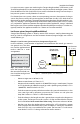
Low Pressure Series Systems
Series systems are the most commonly used layout for
black steel pipe installations with low pressure supplies. In
series layouts, a main run from the gas source is branched
with tees to each appliance. The service pressure down-
stream of the meter is typically less than ½ PSI.
It is important to consider
the minimum pressure
supplied to any given
appliance in a series layout.
Most natural gas appli-
ances require a minimum
of 4" w.c. pressure, while LP
appliances require a mini-
mum of 10" w.c. pressure.
Local code restrictions may
dictate allowable pressure
drop along any particular
run.
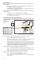
Low Pressure Parallel
Systems
Parallel systems have a
central distribution mani-
fold with branch runs to
the appliances. Typically, a
main supply line is run
from the gas supply to a
manifold and "home runs"
are routed to each appli-
ance location. Manifold
stations are located as
close as possible to the
appliance(s) with the
greatest load. Parallel lay-
outs are most commonly
used in ¼ to ½ PSI systems.
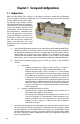
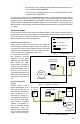
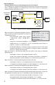
Appliance Shut-off Valve
Shut-off Valve
Pressure Regulator
Manifold
Figure 3.1 Routing Diagram Key
Gas
Meter
Water
Heater
25,000 BTUH
Range Oven
40,000 BTUH
Low Pressure
(5 - 7" w.c.)
Figure 3.2 A low pressure series layout
Gas
Meter
25,000 BTUH
Range Oven
40,000 BTUH
Low Pressure
(5 - 7" w.c.)
60,000 BTUH
Water
Heater
Furnace
Figure 3.3 A low pressure parallel layout