
Installation Guide


32
Installation Practices
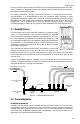
Non-movable outdoor appliances, such as
xed barbecues, gas lights, or heaters can be
directly connected with HOME-FLEX® so long
as such connections are permissible by local
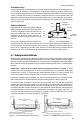
code. On a deck, the outdoor portion of the
tubing run must be supported against the
sides of joists. If the deck elevation is below
the building foundation, exposed tubing
must be routed through a protective water-tight nonmetallic conduit. Underground tubing
runs must follow the guidelines in Section 4.9 (p. 35). The exposed end of conduit must be
sealed to prevent foreign objects (dirt, water, pests, etc.) from entering. (Figure 4.21 and Fig-
ure 4.20)
Fireplace Installations
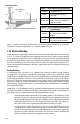
Most gas replaces and gas logs are con-
sidered xed appliances which can be
directly connected with HOME-FLEX®
without a special termination ange (ANSI
Z24.50). Direct delivery of gas is approved
to the key valve for decorative and heat
generating replaces and for gas logs
used in masonry and pre-fabricated re-
places. (Figure 4.22)
DO NOT use HOME-FLEX® CSST to connect
gas log lighter or gas wands for use in all-
fuel (wood burning) replaces. For gas log
lighter installations in all-fuel replaces,
HOME-FLEX® must be terminated at the
key valve or another location outside the replace. The nal attachment to the lighter should
be made using black steel pipe.
Should HOME-FLEX® need to be installed through masonry materials in the replace con-
struction, the yellow jacket should remain intact and the HOME-FLEX® tubing should be
routed through a nonmetallic sleeve appropriate for the application. Sleeves are not required
for routing through ceramic liner in heat generating replaces. Spaces between the jack-
et and penetration at interior and/or exterior locations can be caulked. The jacket can be
removed inside the rebox.
Attachment to the HOME-FLEX® system is usually made at the replace shut-o valve, often
located in the control area beneath the burner unit or at the side of the log set. HOME-FLEX®
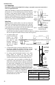
Figure 4.20 Fixed Outdoor Appliance (Underground Routing)
Termination Fitting
90° Elbow
Shut-off Valve
Small gab between conduit and
tting is permitted
Seal against water entry with
compound non-corrosive to stain-
less steel
Protection required up to 6
ft. above ground
Appliance Pedestal/Post
CSST
1" Max
PVC or PE Conduit*
Minimum burial depth 12” or in
compliance with local code
Recommended minimum bend radius: 6”
*ID of conduit should be at least 1/2” greater than OD of CSST
Note: Connection of CSST to equipment gas controls shall
be in accordance with the manufacturer’s instructions
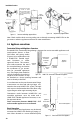
Figure 4.21 Fixed Outdoor Appliance (Deck Mounted)
Diameter of hole shall be at least 1/2 in. greater
than OD of tubing and shall be sleeved and
sealed in accordance with local building code
(if applicable)
Connection of CSST to grill controls/shut-off
valve shall be in accordance with the manufac-
turer’s instructions
Note: CSST shall be installed only on
inside surfaces of joists at the centerline
Outdoor Wooden
Deck
House Foundation
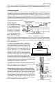
Figure 4.22 Routing to Masonry Fireplace
CSST through
stud walls
Sleeve (if
required)
CSST through
basement or
crawl space