
Installation Guide
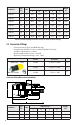
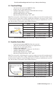
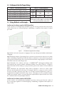


Table Of Contents
- Chapter 1: Introduction
- Chapter 2: Description of System Components
- Chapter 3: System Configuration and Sizing
- Chapter 4: Installation Practices
- Chapter 5: Sizing/Capacity Tables
10
Chapter 3: System Configuration and Sizing
3.1 Configuration
Prior t
o piping installation, refer to building plans or prepare a sketch (this may be required by
the local authority having jurisdiction for permitting purposes) showing the location of the
appliances, the various appliance load demands, point of delivery (gas meter or 2nd stage LP
regulator) and planned piping routes. Appliance load demand data can be obtained from the
manufacturer’s name-plate located on each appliance, or provided to the system designer by
the builder/contractor.
Determine local piping restrictions prior to installing the underground piping system. Con-
firm that the AHJ (local authority having jurisdiction) has accepted the use of medium density
polyethylene (MDPE listed to ASTM D2513) gas piping and fittings listed to ASTM
D2513 / F1924 . MDPE has been accepted by most major code bodies, but state and/or
local adoptions of these codes often lag behind.
Determine metered supply pressure:
• Natural Gas: Check with local gas utility to determine pressure supplied by the meter.
• Verify that the meter's capacity is sufficient to supply the total demand of the system
and appliances." For example, if the maximum capacity of the meter is 250,00 BTUH
and the maximum load of the appliances is in excess of 300,000 BTUH, then the meter
will have to be upgraded. Consult with your gas utility company.
• Verify that the regulator has sufficient capacity to meet the total demands of the
system and appliances
• Liquefied Petroleum Gas (LP Gas, also called Propane): Check with LP supplier to
deter-mine pressure supplied by the first and second stage regulators.
Informational Notes:
• Natural gas pressures: Typical natural gas appliances require 5 inches of water column
(inches of water column is a measurement of pressure that uses a different scale to
more accurately measure low pressure gas – i.e. ¼ PSI = 6.921 inches of water column).
In the past, standard low pressure was typically provided at 6-7 inches of water column
by the meter (and still is in many places) thus allowing for a 1” WC pressure drop. With
the popularity of on-demand water heaters, commercial type cook stoves, and gas
appliances in general, many utilities now provide 2 PSI of pressure from the outlet of
the meter. Because there is no national standard for meter outlet pressures, it is critical
to contact the utility to determine the pressure. Please note that when the outlet pres-
sure of the meter is 2 PSI a line pressure regulator must be placed in the piping system
upstream from the connection of a manifold or appliance.
• LP gas: Check with both the AHJ and LP supplier for their acceptance of MDPE piping.
Determine the total capacity needed for all appliances. The capacity tables within this guide
should be used to determine pipe sizes necessary to meet BTUH input load requirements.
With respect to gas pipe sizing, the intent of all model codes is to ensure there is sufficient gas
volume and gas pressure supplied to the appliance for proper operation. Language from the
International Fuel Gas Code clearly illustrates this point:
Allowable Pressure Drop: The design pressure loss on any piping system under maxi-
mum probable ow conditions, from the point of delivery to the inlet connection of
the equipment, shall be such that supply pressure at the equipment is greater than the
minimum required for proper equipment operation.
Important Considerations:
• All existing pipe sizes within a gas piping system should be evaluated and confirmed
to be adequate to handle the additional load when adding additional appliances.
• Allowable pressure drop along any particular run may be dictated by local code
restrictions.
• Call 811 at least 3 days prior to digging.