
Installation Guide


18 19
PLOW ASSEMBLY
Manual Lift Assembly (Models 23100/23150)
Parts needed: L, O, P, Q, S, T
17.
Align lift frame (L) to A-Frame (N)
by inserting two 1 x 3" pins. Lock
pins using ¼ x 2" cotter pins and
bend cotter pins to lock into place.
18
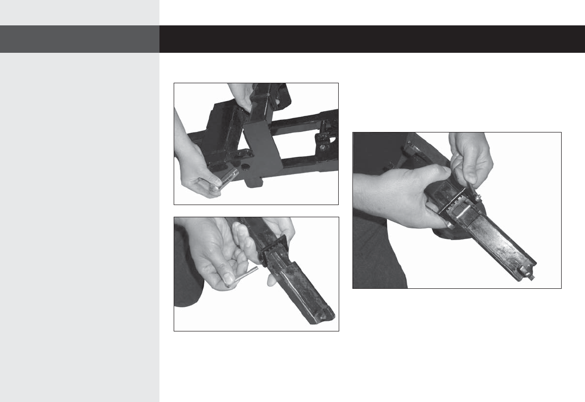
18.
Attach manual latch (P) to manual latch
weldment (Q) using 1/4-20 x 2-1/2"
and 1/4-20 locknut.
19.
Snug fasteners using a 7/16" box wrench and a 7/16" ratchet wrench.
NOTE: The manual latch rung lock and manual latch weldment
should be able to hinge.