
How to Guide

Assembly
Instructions
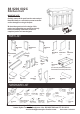
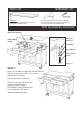
UNIT PART LIST
N1.
Front Part
2 pcs.
N3.
Side Part
2 pcs.
N4.
Side Part
2 pcs.
N5.
Bottom
2 pcs.
N2.
Back Part
2 pcs.
N2
N2
N5
N5
N3
N4
N4
N4
N3
N3
N1
N1
N1
Figure 2
Figure 3
Figure 4
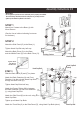
Assemble the Pull Handle
with Machine Screw on
the Front Part (N1).
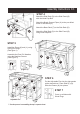
Turn the assembled drawer over and slide the
Plywood Bottom Part (N5) into the grooves
on Side Parts (N3) and (N4). Be sure to push
the plywood all the way forward so it meets the
Front Part (N1).
HARDWARE LIST
Pull Handle
2 pcs.
Machine Screw
for Pull Handle
4 pcs.
Wood Screw / ”
1
2
(for Bottom Part)
12 pcs.
Wood Screw 1”
(for Side Part)
16 pcs.
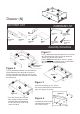
Drawer (N)
N1
N2
N3
N5
N4
Figure 1
Line up Side Parts (N3) and (N4) to the Front Part
(N1) and Back Part (N2). Be sure to follow the
‘Arrow’ sign sticker on the parts.
Using a screw driver, insert 1” screwsPhillip’s
into each of the 4 pre-drilled holes on Side Parts
(N3) and (N4), then tighten half way.
Insert the remaining (6) 1/2” screws
into the pre-drilled holes on Bottom Part
(N5), then tighten all screws
MAKE SURE ROLLER
IS ON THE BACK
* If you are missing any of these
parts, please contact our DMI
Customer Service Department
at 1-877-831-0319 or fax us at
1-800-755-2878.
Figure 1
Figure 2
Figure 3
Figure 4