OPERATOR’S MANUAL MightyLite 26cc Edger UT50500/UT50901 (ALL VERSIONS) Your edger has been engineered and manufactured to our high standard for dependability, ease of operation, and operator safety. Properly cared for, it will give you years of rugged, trouble-free performance. WARNING: To reduce the risk of injury, the user must read and understand the operator’s manual before using this product. Thank you for your purchase.
TABLE OF CONTENTS Introduction....................................................................................................................................................................... 2 General Safety Rules......................................................................................................................................................3-4 Specific Safety Rules...............................................................................................................
important safety instructions DANGER – When using your edger trimmer, follow basic precautions. DANGER – Rotating Cutting MEMBER: • Keep both hands on handles when blade is rotating. • Keep feet away from cutting area. WARNING: • Do not attempt to remove cut material nor hold material to be cut when engine is running or when cutting member is moving. Read and understand all instructions. Failure to follow all instructions listed below may result in electric shock, fire and/or serious personal injury.
important safety instructions Service on the product must be performed by qualified repair personnel only. Service or maintenance performed by unqualified personnel could result in injury to the user or damage to the product. Use only identical replacement parts when servicing the product. Use of unauthorized parts may create a risk of serious injury to the user, or damage to the product. SPECIFIC SAFETY RULES Be sure all guards are properly and securely attached.
SYMBOLS Some of the following symbols may be used on this product. Please study them and learn their meaning. Proper interpretation of these symbols will allow you to operate the product better and safer. SYMBOL NAME EXPLANATION Safety Alert Symbol Precautions that involve your safety. Read the Operator’s Manual To reduce the risk of injury, user must read and understand operator’s manual before using this product.
SYMBOLS The following signal words and meanings are intended to explain the levels of risk associated with this product. SYMBOL SIGNAL MEANING DANGER: Indicates an imminently hazardous situation, which, if not avoided, will result in death or serious injury. WARNING: Indicates a potentially hazardous situation, which, if not avoided, could result in death or serious injury. CAUTION: Indicates a potentially hazardous situation, which, if not avoided, may result in minor or moderate injury.
FEATURES FEATURES PRODUCT SPECIFICATIONS Weight (dry)................................................................................................................................................................14.5 lbs. Engine Displacement.......................................................................................................................................................26cc Blade Length......................................................................................................
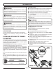
FEATURES KNOW YOUR edger TOP-MOUNTED MOTOR See Figure 1. The safe use of this product requires an understanding of the information on the tool and in this operator’s manual as well as a knowledge of the project you are attempting. Before use of this product, familiarize yourself with all operating features and safety rules. The top-mounted motor improves balance and is located away from the dust and debris of the cutting area. ASSEMBLY UNPACKING This product requires assembly.
ASSEMBLY NOTE: If the button does not release completely in the positioning hole, the shafts are not locked into place. Slightly rotate from side to side until the button is locked into place. Tighten the knob securely. FRONT HANDLE WARNING: Be certain the knob is fully tightened before operating equipment; check it periodically for tightness during use to avoid serious personal injury. removing the attachment from the power head For removing or changing the attachment: Loosen the knob.
OPERATION FILLING TANK WARNING: Clean surface around fuel cap to prevent contamination. Do not allow familiarity with this product to make you careless. Remember that a careless fraction of a second is sufficient to inflict serious injury. Set product on its side so that the spout points up. Loosen fuel cap slowly. Rest the cap on a clean surface. Carefully pour fuel into the tank. Avoid spillage. Immediately replace fuel cap and hand tighten. Wipe up any fuel spillage.
OPERATION To start a warm engine: Slowly press the primer bulb seven (7) times. Pull the starter grip sharply until the engine runs. PRIMER BULB TO STOP THE ENGINE: See Figure 4. Release the throttle trigger and push STOP on the ON/OFF switch. if assistance is required STARTING THIS product: Do not return this product to the retail store where it was purchased. Please call our Customer Service Department for any issues you may have.
OPERATION ADJUSTING DEPTH OF CUT See Figures 7 - 8. The depth of cut is determined by the distance from the bottom of the wheel to the tip of blade. adjusting knob to increase depth To adjust the blade depth: Stop the engine. Disconnect the spark plug wire and move it away from spark plug. Loosen the adjusting knob and move the wheel arm up to increase the depth or down to decrease the depth. wheel arm After adjustment is complete, tighten the adjusting knob securely.
MAINTENANCE WARNING: upper flange washer When servicing, use only identical replacement parts. Use of any other parts may create a hazard or cause product damage. gear case WARNING: slots Always wear safety goggles or safety glasses with side shields during product operation. If operation is dusty, also wear a dust mask. flange lower flange washer WARNING: Fig.
MAINTENANCE Using a 1/2 in. socket wrench, turn the blade nut counterclockwise onto the edger shaft and tighten securely. NOTE: Always make sure the blade is correctly installed and securely fastened before each use. replacing the DEBRIS FLAP hex nut edger guard washer See Figure 12. Replace the debris flap if it is worn. Stop the engine. Disconnect the spark plug wire and move it away from spark plug. Using a 10 mm wrench or socket, remove the hex nuts, washers, and debris flap.
MAINTENANCE CLEANING THE AIR FILTER SCREEN See Figures 14 - 15. For proper performance and long life, keep the air filter screen clean. choke dial cover Remove the hex nut, wavy washer, flat washer, and choke dial cover. Brush the air filter screen lightly to clean. Reinstall the choke dial cover, flat washer, wavy washer, and hex nut. Tighten hex nut to secure. wavy washer FUEL CAP WARNING: A leaking fuel cap is a fire hazard and must be replaced immediately.
TROUBLESHOOTING Problem Engine will not start. Possible Cause Solution No spark. Check spark. Remove spark plug. Reattach the spark plug cap and lay spark plug on metal cylinder. Pull the starter rope and watch for spark at spark plug tip. If there is no spark, repeat test with a new spark plug. No fuel. Push primer bulb until bulb is full of fuel. If bulb does not fill, primary fuel delivery system is blocked. Contact a servicing dealer.
TROUBLESHOOTING Problem Lubricant drips from muffler. Possible Cause Solution Operating edger at part throttle. Operate edger at full throttle. Check lubricant/fuel mixture. Use fresh fuel and the correct 2-cycle lubricant mix. Air filter dirty. Clean air filter. Refer to Cleaning the Air Filter Screen earlier in this manual. idle speed screw SLOW FAST Fig.
WARRANTY LIMITED WARRANTY STATEMENT Homelite Consumer Products, Inc., (“Homelite”) warrants to the original retail purchaser that this HOMELITE brand outdoor product is free from defect in material and workmanship and agrees to repair or replace, at Homelite’s, discretion, any defective product free of charge within these time periods from the date of purchase.
WARRANTY The following California Air Resources Board (CARB) statement only applies to model numbers required to meet the CARB requirements. Homelite consumer products, INC., LIMITED WARRANTY STATEMENT FOR FEDERAL AND CALIFORNIA EMISSION CONTROL SYSTEMS NON-ROAD AND SMALL OFF-ROAD ENGINES YOUR WARRANTY RIGHTS AND OBLIGATIONS The U.S. Environmental Protection Agency (EPA), the California Air Resources Board (CARB), and Homelite Consumer Products, Inc.
WARRANTY this product was manufactured with a catalyst muffler Congratulations! You have made an investment toward protecting the environment. In order to maintain this product’s original emission level, please refer to the maintenance section below. EMISSIONS MAINTENANCE SCHEDULE AND WARRANTED PARTS LIST Emissions Parts Inspect Before Clean Every Each Use 5 Hours Replace Every 25 Hours or Yearly Clean Every 25 Hours or Yearly Replace Every 50 Hours CATALYTIC MUFFLER ASSEMBLY.......................
NOTES
OPERATOR’S MANUAL MightyLite 26cc Edger UT50500/UT50901 (ALL VERSIONS) WARNING: The engine exhaust from this product contains chemicals known to the State of California to cause cancer, birth defects or other reproductive harm. CALIFORNIA PROPOSITION 65 • Parts and Service Prior to requesting service or purchasing replacement parts, please obtain your model and serial number from the product data plate.