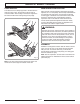
OPERATOR'S MANUAL 16 in. (406 mm) 38cc Chain Saw Model No. UT10927A Your new chain saw has been engineered and manufactured to Homelite’s high standard for dependability, ease of operation, and operator safety. Properly cared for, it will give you years of rugged, trouble-free performance. WARNING: To reduce the risk of injury, the user must read and understand the operator’s manual. Thank you for buying a Homelite chain saw.
TABLE OF CONTENTS ■ Introduction ...................................................................................................................................................................... 2 ■ General Safety Instructions .......................................................................................................................................... 3-4 ■ Specific Safety Instructions ..........................................................................................................
GENERAL SAFETY RULES ■ DO NOT OPERATE A CHAIN SAW WITH ONE HAND. Serious injury to the operator, helpers, bystanders, or any combination of these persons may result from one-handed operation. A chain saw is intended for two-handed use. WARNING: The warnings, labels, and instructions found in this section of the operator's manual are for your safety. Failure to follow all instructions may result in serious personal injury.
GENERAL SAFETY RULES ■ ALL CHAIN SAW SERVICE, other than the items listed in the instruction manual and all maintenance, should be performed by competent chain saw service personnel. (For example, if improper tools are used to remove the flywheel or if an improper tool is used to hold the flywheel in order to remove the clutch, structural damage to the flywheel could occur and subsequently could cause the flywheel to burst.) ■ KEEP ALL PARTS OF YOUR BODY away from the saw chain when the engine is running.
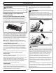
SPECIFIC SAFETY RULES PUSH AND PULL MAINTENANCE PRECAUTIONS The reaction force is always opposite to the direction the chain is moving. Thus, the operator must be ready to control the PULL when cutting on the bottom edge of the bar and the PUSH when cutting along the top edge. Never operate a chain saw that is damaged, improperly adjusted, or is not completely and securely assembled. Be sure that the saw chain stops moving when the throttle control trigger is released.
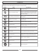
SYMBOLS Important: Some of the following symbols may be used on your tool. Please study them and learn their meaning. Proper interpretation of these symbols will allow you to operate the tool better and safer. SYMBOL NAME EXPLANATION Safety Alert Symbol Indicates danger, warning or caution. It means attention!!! Your safety is involved.
SYMBOLS The purpose of safety symbols is to attract your attention to possible dangers. The safety symbols, and the explanations with them, deserve your careful attention and understanding. The safety warnings do not by themselves eliminate any danger. The instructions or warnings they give are not substitutes for proper accident prevention measures. Symbol Meaning DANGER: Indicates an imminently hazardous situation which, if not avoided, will result or serious injury.
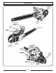
FEATURES TRIGGER RELEASE CHAIN OIL CAP FRONT HAND GUARD/CHAIN BRAKE FRONT HANDLE SAFE-T-TIP® CYLINDER COVER CHOKE LEVER PRIMER BULB STARTER GRIP STARTER/FAN HOUSING REAR HANDLE STOP ON/OFF SWITCH Page 8 FUEL MIX CAP THROTTLE TRIGGER Fig.
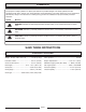
OPERATION The chain brake should be cleaned and tested daily. Refer to “Operation” later in this manual for additional information. WARNING: The warnings and instructions in this section of the operator's manual are for your safety and to prevent serious personal injury. WARNING: Even with daily cleaning of the mechanism, the dependability of a chain brake to perform under field conditions cannot be certified. Keep the SAFE-T-TIP nose guard on your saw's guide bar and use proper cutting techniques.
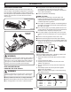
OPERATION KICKBACK PRECAUTIONS Rotational kickback occurs when the moving chain contacts an object at the Kickback Danger Zone of the guide bar. The result is a lightning fast, reverse reaction which kicks the guide bar up and back towards the operator. This reaction can cause loss of control which can result in serious injury. KICKBACK DANGER ZONE Fig. 6 ROTATIONAL KICKBACK Fig. 7 WARNING: Always shut off engine before fueling. Never add fuel to a machine with a running or hot engine.
OPERATION STARTING THE ENGINE WARNING: Keep your body to the left of the chain line. Never straddle the saw or chain, or lean over past the chain line. STOP Fig. 8 ADDING OIL 1. Place the chain saw on level ground and ensure that no objects or obstructions are in the immediate vicinity that could come in contact with the bar and chain. 2. Hold the front handle firmly with the left hand and put your right foot onto the base of the rear handle. See Figure 10. Use HOMELITE Bar and Chain Oil.
OPERATION STARTING A COLD ENGINE: 3. Move the chain brake to the BRAKE position. Note: Set the chain brake by pushing the chain brake lever/hand guard forward (towards the bar), to the brake position. Refer to “Operation – Operating Chain Brake” for additional information. 4. Set the ignition switch to the RUN (I) position. 5. Fully press and release the PRIMER BULB 7 times. 6. Pull CHOKE lever all the way OUT to full position.
OPERATION 7. Pull STARTER until engine attempts to start. Slowly pull the starter grip out for a short distance until you feel the starter engage, then briskly pull straight up. Do not pull to the end of the rope, this can damage the starter. Hold onto the grip during rewinding (see figure 16). Pull the starter rope until the first firing of the engine is heard (no more than five pulls). Note: A new unit may require additional pulls. 8. Push CHOKE lever all the way IN. 9. Pull STARTER until engine runs.
OPERATION PREPARING FOR CUTTING PROPER GRIP ON HANDLES Refer to “Specific Safety Rules – Safety Apparel” earlier in this manual for appropriate safety equipment. ■ Wear non-slip gloves for maximum grip and protection. ■ Hold the saw firmly with both hands. Always keep your LEFT HAND on the front handle and your RIGHT HAND on the rear handle so that your body is to the left of the chain line.
OPERATION BASIC OPERATING/CUTTING PROCEDURES ADJUSTING THE CARBURETOR Practice cutting a few small logs using the following technique to get the “feel” of using your saw before you begin a major sawing operation. 1. Take the proper stance in front of the wood with the saw idling. 2. Accelerate the engine to full throttle just before entering the cut by squeezing the throttle trigger. 3. Begin cutting with the saw against the log. 4. Keep the engine at full throttle the entire time you are cutting. 5.
OPERATION ADJUSTING IDLE SPEED OPERATING THE CHAIN BRAKE ■ If the engine starts, runs, and accelerates but will not idle, turn the idle speed screw “ T ” clockwise to increase idle speed. ■ If the chain turns at idle, turn the idle speed screw “ T ” counterclockwise to reduce the idle RPM and stop the chain movement. If the saw chain still moves at idle speed, contact a Homelite Service Center for adjustment and discontinue use until the repair is made.
OPERATION FELLING TREES HAZARDOUS CONDITIONS WARNING: Do not fell trees during periods of high wind or heavy precipitation. Wait until the hazardous weather has ended. When felling a tree, it is important that you heed the following warnings to prevent possible serious injury. PLANNED LINE OF FALL ■ Do not cut down trees having an extreme lean or large trees with rotten limbs, loose bark, or hollow trunks. Have these trees pushed or dragged down with heavy equipment, then cut them up.
OPERATION PROPER PROCEDURE FOR TREE FELLING 1. Pick your escape route (or routes in case the intended route is blocked). Clear the immediate area around the tree and make sure there are no obstructions in your planned path of retreat. Clear the path of safe retreat approximately 135° from the planned line of fall. 2. Consider the force and direction of the wind, the lean and balance of the tree, and the location of large limbs. These things influence the direction in which the tree will fall.
OPERATION REMOVING BUTTRESS ROOTS A buttress root is a large root extending from the trunk of the tree above the ground. Remove large buttress roots prior to felling. Make the horizontal cut into the buttress first, followed by the vertical cut. Remove the resulting loose section from the work area. Follow the correct tree felling procedure after you have removed the large buttress roots. Refer to “Operation – Proper Procedure for Felling Trees” earlier in this manual.
OPERATION BUCKING LOGS UNDER STRESS Make the first bucking cut 1/3 of the way through the log and finish with a 2/3 cut on the opposite side. As you cut the log, it will tend to bend. The saw can become pinched or hung in the log if you make the first cut deeper than 1/3 of the diameter of the log. Give special attention to logs under stress to prevent the bar and chain from pinching. LOG SUPPORTED AT ONE END FINISHING CUT LOAD OVERBUCKING See Figure 38.
OPERATION LIMBING AND PRUNING ■ Work slowly, keeping both hands on the saw with a firm grip. Maintain secure footing and balance. ■ Keep the tree between you and the chain while limbing. Cut from the side of the tree opposite the branch you are cutting. ■ Do not cut from a ladder, this is extremely dangerous. Leave this operation for professionals. ■ Do not cut above chest height as a saw held higher is difficult to control against kickback.
MAINTENANCE ASSEMBLING THE BAR AND CHAIN DANGER: Never start the engine before installing the guide bar, chain, drivecase cover, and clutch drum. Without all these parts in place, the clutch can fly off or explode exposing the user to possible serious injury. COMBINATION WRENCH WARNING: To avoid serious personal injury, read and understand all the safety instructions in this section. BAR MOUNTING NUTS Fig. 42 1. Always place the switch in the stop “ O ” position before you work on the saw. 2.
MAINTENANCE 6. Lay out the saw chain in a loop and straighten any kinks. The cutters should face in the direction of chain rotation. If they face backwards, turn the loop over. See Figure 45. 7. Place the chain drive links into the bar groove as shown in figure 46. 8. Position the chain so there is a loop at the back of the bar. 9. Hold the chain in position on the bar and place the loop around the sprocket. 10.
MAINTENANCE 11. Replace the outer guide bar plate ensuring that the bar pin groove is at the bottom with the upper and lower edges angled away from the guide bar. 12. Replace the clutch cover and bar mounting nuts. 13. Tighten the bar mounting nuts finger tight only. The bar must be free to move for tension adjustment. 14. Remove all slack from the chain by turning the chain tensioning screw clockwise until the chain seats snugly against the bar with the drive links in the bar groove. 15.
MAINTENANCE ADJUSTING THE CHAIN TENSION WARNING: Never touch or adjust the chain while the motor is running. The saw chain is very sharp. Always wear protective gloves when performing maintenance on the chain. 1. Stop the engine before setting the chain tension. 2. Make sure the guide bar nuts are loosened to finger tight, turn the chain tensioner clockwise to tension the chain.
MAINTENANCE ■ Raker (depth gauge) clearance. See Figure 55. 1. Too low increases the potential for kickback. 2. Not low enough decreases cutting ability. ■ If the cutter teeth hit hard objects such as nails and stones, or are abraded by mud or sand on the wood, have the Homelite Service Center sharpen the chain. Note: Inspect the drive sprocket for wear or damage when replacing the chain.
MAINTENANCE CHECK FOR WEAR OR DAMAGE LEFT HAND CUTTERS RIGHT HAND CUTTERS Fig. 62 Fig. 59 CAUTION: A dull or improperly sharpened chain can cause excessive engine speed during cutting which may result in severe engine damage. WARNING: Improper chain sharpening increases the potential of kickback. Fig. 60 WARNING: Failure to replace or repair a damaged chain can cause serious injury. WARNING: The saw chain is very sharp. Always wear protective gloves when performing maintenance to the chain. Fig.
MAINTENANCE TOP PLATE FILING ANGLE SIDE PLATE FILING ANGLE ■ CORRECT 30° - file holders are marked with guide marks to align file properly to produce correct top plate angle. ■ LESS THAN 30° – for cross cutting. ■ MORE THAN 30° – feathered edge dulls quickly. 80° CORRECT SIDE PLATE ANGLE ■ CORRECT 80o – Produced automatically if you use the correct diameter file in the file holder. ■ HOOK – “Grabs” and dulls quickly, increases the potential of KICKBACK.
MAINTENANCE MAINTAINING THE SAFE-T-TIP® NOSE GUARD RESTORE ORIGINAL SHAPE BY ROUNDING THE FRONT CAUTION: Make sure the chain has stopped before you do any work on the saw. Fig. 67 WARNING: Although the guide bar comes with a SAFE-T-TIP® anti-kickback device already installed, you need to check the tightness of the mounting screw before each use. MAINTAINING THE GUIDE BAR CAUTION: Make sure the chain has stopped before you do any work on the saw.
MAINTENANCE ■ Clean the pre-filter every 25 tanks of fuel or sooner, if required. Remove the cylinder cover, starter assembly and the fan housing baffle for access to the pre-filter in the engine housing. Note: If you use an air hose for drying, blow through both sides of filter. TIGHTEN 3/4 OF A TURN CAUTION: Fig. 70 MOUNTING THE SAFE-T-TIP® NOSE GUARD Never run the engine without the air filter, serious damage could result.
MAINTENANCE CLEANING THE STARTER UNIT Use a brush or compressed air to keep the cooling vents of the starter assembly free and clean of debris. CLEAN FLYWHEEL FINS P STO Fig. 76 CHECKING THE FUEL FILTER Fig. 74 Check the fuel filter periodically. Replace it if contaminated or damaged. CLEANING THE ENGINE Clean the cylinder fins and flywheel fins with compressed air or a brush periodically. Dangerous overheating of the engine may occur due to impurities on the cylinder.
MAINTENANCE CLEANING THE SPARK ARRESTING MUFFLER CHAIN CATCHER The muffler is equipped with a spark arrestor screen. A faulty spark arrestor screen can create a fire hazard. Through normal use the screen can become dirty and should be inspected weekly and cleaned as required. Always keep the muffler and spark arrestor on your saw in good condition. WARNING Muffler surfaces are very hot during and after operation of the chain saw, keep all body parts away from the muffler.
BAR AND CHAIN COMBINATIONS Length of Bar Guide Bar Part Number Chain Part Number 16 in. UP08676 UP08677 18 in. UP08679 UP08680 TROUBLESHOOTING PROBLEM Engine will not start. (Make sure ignition switch is in start position “I”.) POSSIBLE CAUSE SOLUTION 1. Check spark. Remove air filter cover. Remove spark plug from cylinder. Reattach the spark plug wire and lay spark plug on top of cylinder with the metal part of plug touching the cylinder.
TROUBLESHOOTING PROBLEM POSSIBLE CAUSE SOLUTION Engine starts, runs, and accelerates but will not idle. Carburetor requires adjustment. Turn idle speed screw “T” clockwise to increase idle speed. If chain turns at idle, turn idle speed screw “T” counterclockwise to decrease speed. Wear protective equipment and observe all safety instructions. See Figure 26. Bar and chain running hot and smoking. 1. Chain oil tank empty. 1. Oil tank should be filled every time that fuel tank is filled. 2.
WARRANTY LIMITED WARRANTY STATEMENT Homelite Consumer Product, Inc. warrants to the original retail purchaser that this HOMELITE product is free from defect in material and workmanship and agrees to repair or replace, at Homelite Consumer Products, Inc.'s discretion, any defective product free of charge within these time periods from the date of purchase.
OPERATOR'S MANUAL 16 in. (406 mm) 38cc Chain Saw Model No. UT10927A WARNING: The engine exhaust from this product contains chemicals known to the State of California to cause cancer, birth defects or other reproductive harm. CALIFORNIA PROPOSITION 65 For product information, technical help, dealer locations or parts ordering information visit our website at: www.homelite.com. HOMELITE CONSUMER PRODUCTS, INC.