OPERATOR’S MANUAL 356 mm (30 ft.) 33cc Chainsaw CSP3314 Model No. UT74121A Your new chainsaw has been engineered and manufactured to Homelite’s high standard for dependability, ease of operation and operator safety. Properly cared for, it will give you years of rugged, trouble-free performance. WARNING: To reduce the risk of injury, the user must read and understand the operator’s manual. Thank you for buying a Homelite chainsaw.
TABLE OF CONTENTS Introduction ..................................................................................................................................................................... 2 General Safety Rules ................................................................................................................................................... 3-4 Specific Safety Rules.......................................................................................................................
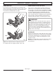
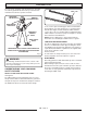
GENERAL SAFETY RULES 3. Make sure the area in which you are cutting is free from obstructions. DO NOT let the nose of the guide bar contact a log, branch, fence or any other obstruction which could be hit while you are operating the saw. WARNING: The warnings, labels and instructions found in this section of the operator’s manual are for your safety. Failure to follow all instructions may result in serious personal injury. 4. Cut at high engine speeds. Always cut with the engine running at full speed.
GENERAL SAFETY RULES KEEP ALL PARTS OF YOUR BODY away from the saw chain when the engine is running. ALWAYS CARRY THE CHAINSAW WITH THE ENGINE STOPPED AND THE BRAKE ENGAGED, the guide bar and saw chain to the rear, and the silencer away from your body. When transporting the chainsaw, use the appropriate guide bar scabbard. DO NOT OPERATE A CHAINSAW THAT IS DAMAGED, improperly adjusted, or not completely and securely assembled.
SPECIFIC SAFETY RULES WARNING: The warnings, labels and instructions found in this section of the operator’s manual are for your safety. Failure to follow all instructions may result in serious personal injury. Wear non-slip safety footwear and heavy-duty gloves to improve your grip and to protect your hands. Wear eye, hearing and head protection when operating this equipment. REFUELLING (DO NOT SMOKE!) To reduce the risk of fire and burn injury, handle fuel with care. It is highly flammable.
SPECIFIC SAFETY RULES PUSH AND PULL MAINTENANCE PRECAUTIONS The reaction force is always opposite to the direction the chain is moving. Thus, the operator must be ready to control the PULL when cutting on the bottom edge of the bar and the PUSH when cutting along the top edge. Never operate a chainsaw that is damaged, improperly adjusted, or is not completely and securely assembled. Be sure that the saw chain stops moving when the throttle control trigger is released.
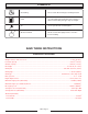
SYMBOLS Important: Some of the following symbols may be used on your tool. Please study them and learn their meaning. Proper interpretation of these symbols will allow you to operate the tool better and more safely. SYMBOL NAME Safety Alert Symbol Indicates danger, warning or caution. It means attention!!! Your safety is involved.
SYMBOLS No Smoking Do not smoke when mixing fuel or filling fuel tank. Petrol Use unleaded petrol intended for motor vehicle use with an octane rating of 87 ([R + M] / 2) or higher. Oil Use 2-cycle oil for air cooled engines. Mix Petrol and Oil Mix the fuel mix thoroughly and also each time before refuelling. SAVE THESE INSTRUCTIONS SPECIFICATIONS Weight - No bar, chain, fuel or oil .............................................................................................................. 4.
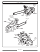
FEATURES TRIGGER RELEASE THROTTLE LOCK BUTTON FRONT HAND GUARD/CHAIN BRAKE SILENCER FRONT HANDLE CHAIN OIL CAP SAFE-T-TIP CYLINDER COVER CHAIN CATCHER CHOKE LEVER PRIMER BULB CARBURETTOR ADJUSTMENT STARTER GRIP STARTER/FAN HOUSING REAR HANDLE ON/OFF SWITCH FUEL MIX CAP UK - Page 9 THROTTLE TRIGGER Fig.
OPERATION For your safety, study this entire manual before operating the saw. Pay particular attention to the precautions and instructions listed in the operator’s manual. WEAR HEAD PROTECTION WEAR EYE PROTECTION Fig. 4 WEAR HEARING PROTECTION WEAR “NON-SLIP” GLOVES SAFE-T-TIP Users, such as professional loggers who need to draw the tip through the cut, make boring cuts, or cut logs bigger than the bar length, should reinstall the SAFE-T-TIP as soon as those cuts are complete.
OPERATION CHAIN BRAKE Chain brakes are designed to quickly stop the chain from rotating. When the chain brake lever/hand guard is pushed towards the bar, the chain should stop immediately. A chain brake does not prevent kick-back. The chain brake should be cleaned and tested daily. Refer to “Operation” later in this manual for additional information. WARNING: Even with daily cleaning of the mechanism, the dependability of a chain brake to perform under field conditions cannot be certified.
OPERATION WARNING: Always turn off engine before refuelling. Never add fuel to a machine with a running or hot engine. Move at least 9 m (30 ft.) from refuelling site before starting the engine. DO NOT SMOKE! Failure to heed this warning can result in possible personal injury. Mix 2% oil into the petrol. This is a 50:1 ratio. Mix the fuel thoroughly and each time before refuelling. Mix in small quantities. Do not mix quantities larger than usable in a 30-day period.
OPERATION STARTING THE ENGINE See Figures 10 to 19. WARNING: Keep your body to the left of the chain line. Never straddle the saw or chain, or lean over past the chain line. Fig. 8 CHAIN OIL SYSTEM 1. Place the chainsaw on level ground and ensure that no objects or obstructions which could come in contact with the bar and chain are in the immediate vicinity. 2. Hold the front handle firmly with the left hand and put your right foot onto the base of the rear handle. See Figure 9.
OPERATION STARTING A COLD ENGINE: 3. Move the chain brake to the BRAKE position. NOTE: Set the chain brake by pushing the chain brake lever/hand guard forward (towards the bar) to the brake position. Refer to “Operation – Operating the Chain Brake” later in this manual for additional information. 4. Set the ignition switch to the RUN (I) position. 5. Fully press and release the PRIMER BULB 7 times. 6. Pull CHOKE lever all the way OUT to full position. 7. Engage trigger release.
OPERATION 8. Pull STARTER until engine attempts to start. Slowly pull the starter grip out for a short distance until you feel the starter engage, then briskly pull straight up. Do not pull to the end of the rope; this may damage the starter. Hold onto the grip during rewinding. Pull the starter rope until the first firing of the engine is heard (no more than five pulls). NOTE: A new unit may require additional pulls. 9. Push choke lever to half choke position. 10. Pull starter until engine runs.
OPERATION PREPARING FOR CUTTING PROPER GRIP ON HANDLES See Figures 20 and 21. Refer to “Specific Safety Rules – Safety Apparel” earlier in this manual for appropriate safety equipment. Wear non-slip gloves for maximum grip and protection. Hold the saw firmly with both hands. Always keep your LEFT HAND on the front handle and your RIGHT HAND on the rear handle so that your body is to the left of the chain line.
OPERATION BASIC OPERATING/CUTTING PROCEDURES ADJUSTING THE CARBURETTOR Practise cutting a few small logs, using the following technique to get the “feel” of using the saw before you begin a major sawing operation. See Figures 24 and 25. 1. Take the proper stance in front of the wood with the saw idling. 2. Accelerate the engine to full throttle just before entering the cut by squeezing the throttle trigger. Before adjusting the carburettor, clean the air filter and the starter cover vents.
OPERATION ADJUSTING IDLING SPEED OPERATING THE CHAIN BRAKE If the engine starts, runs, and accelerates but will not idle, turn the idling speed screw “T” clockwise to increase idling speed. If the chain turns at idle, turn the idling speed screw “T” anticlockwise to reduce the idling RPM and stop the chain movement. If the saw chain still moves at idling speed, contact a Homelite service dealer for adjustment and discontinue use until the repair is made. WARNING: THE SAW CHAIN SHOULD NEVER TURN AT IDLE.
OPERATION FELLING TREES HAZARDOUS CONDITIONS STAY AWAY FROM ELECTRICAL LINES AND BUILDINGS See Figure 29. WARNING: KEEP BYSTANDERS AWAY Do not fell trees during periods of high wind or heavy precipitation. Wait until the hazardous weather has ended. When felling a tree, it is important that you heed the following warnings to prevent possible serious injury. Wear eye, hearing and head protection when operating this equipment.
OPERATION PROPER PROCEDURE FOR TREE FELLING See Figure 30. PLANNED LINE OF FALL 1. Pick your escape route (or routes in case the intended route is blocked). Clear the immediate area round the tree and make sure there are no obstructions in your planned path of retreat. Clear the path of safe retreat approximately 135° from the planned line of fall. 2. Consider the force and direction of the wind, the lean and balance of the tree, and the location of large limbs.
OPERATION 3. Cut a notch about one-third the diameter of the trunk in the side of the tree. Make the notch cuts so they intersect at right angles to the line of fall. This notch should be cleaned out to leave a straight line. To keep the weight of the wood off the saw, always make the lower cut of the notch before the upper cut. See Figure 31. 4. Make the back-cut level and horizontal, and at a minimum of 5 cm (2 in.) above the horizontal cut of the notch. See Figure 31.
OPERATION REMOVING BUTTRESS ROOTS A buttress root is a large root extending from the trunk of the tree above the ground. Remove large buttress roots before felling. Make the horizontal cut into the buttress first, followed by the vertical cut. Remove the resulting loose section from the work area. Follow the correct tree felling procedure after you have removed the large buttress roots. Refer to “Operation – Proper Procedure for Tree Felling” earlier in this manual.
OPERATION BUCKING LOGS UNDER STRESS Make the first bucking cut one-third of the way through the log and finish with a two-thirds cut on the opposite side. As you cut the log, it will tend to bend. The saw can become pinched or hung in the log if you make the first cut deeper than one-third of the diameter of the log. LOG SUPPORTED AT ONE END FINISHING CUT LOAD Give special attention to logs under stress to prevent the bar and chain from pinching. OVERBUCKING See Figure 38.
OPERATION LIMBING AND PRUNING See Figure 39. Work slowly, keeping both hands on the saw with a firm grip. Maintain secure footing and balance. LOAD Keep the tree between you and the chain while limbing. Cut from the side of the tree opposite the branch you are cutting. Do not cut from a ladder: this is extremely dangerous. Leave this operation for professionals. SECOND CUT FIRST CUT 1/3 DIAMETER Do not cut above chest height, as a saw held higher is difficult to control against kick-back.
MAINTENANCE ASSEMBLING THE BAR AND CHAIN DANGER: Never start the engine before installing the guide bar, chain, drive case cover, and clutch drum. Without all these parts in place, the clutch may fly off or explode, exposing the user to possible serious injury. COMBINATION WRENCH WARNING: To avoid serious personal injury, read and understand all the safety instructions in this section. BAR MOUNTING NUTS Fig. 42 1. Always place the switch in the stop “O” position before you work on the saw. 2.
MAINTENANCE 6. Lay out the saw chain in a loop and straighten any kinks. The cutters should face in the direction of chain rotation. If they face backwards, turn the loop over. See Figure 45. 7. Place the chain drive links into the bar groove. See Figure 46. BAR GROOVE 8. Position the chain so there is a loop at the back of the bar. 9. Hold the chain in position on the bar and place the loop round the sprocket. 10.
MAINTENANCE 11. Replace the outer guide bar plate, ensuring that the bar pin groove is at the bottom with the upper and lower edges angled away from the guide bar. 12. Replace the clutch cover and bar mounting nuts. 13. Tighten the bar mounting nuts finger tight only. The bar must be free to move for tension adjustment. 14. Remove all slack from the chain by turning the chain tensioning screw clockwise until the chain seats snugly against the bar with the drive links in the bar groove. 15.
MAINTENANCE ADJUSTING THE CHAIN TENSION See Figures 52, 53 and 54. WARNING: Never touch or adjust the chain while the motor is running. The saw chain is very sharp. Always wear protective gloves when performing maintenance on the chain. APPROXIMATELY 1.25 mm (0.050 in.) 1. Stop the engine before setting the chain tension. 2. Make sure the guide bar nuts are loosened to finger-tight and turn the chain tensioner clockwise to tension the chain.
MAINTENANCE SHARPENING THE CUTTERS Raker (depth gauge) clearance. See Figure 55. 1. Too low increases the potential for kick-back. 2. Not low enough decreases cutting ability. If the cutter teeth hit hard objects such as nails and stones, or are abraded by mud or sand on the wood, let the Homelite service dealer sharpen the chain. NOTE: Inspect the drive sprocket for wear or damage when replacing the chain.
MAINTENANCE CHECK FOR WEAR OR DAMAGE LEFT-HAND CUTTERS RIGHT-HAND CUTTERS Fig. 62 Fig. 59 CAUTION: A dull or improperly sharpened chain can cause excessive engine speed during cutting which may result in severe engine damage. WARNING: Improper chain sharpening increases the potential of kick-back. Fig. 60 WARNING: Failure to replace or repair a damaged chain can cause serious injury. WARNING: The saw chain is very sharp. Always wear protective gloves when performing maintenance on the chain. Fig.
MAINTENANCE TOP PLATE FILING ANGLE SIDE PLATE FILING ANGLE CORRECT 30° – file holders are marked with guide marks to align file properly to produce correct top plate angle. 80° LESS THAN 30° – for cross cutting. MORE THAN 30° – feathered edge dulls quickly. CORRECT SIDE PLATE ANGLE CORRECT 80o – Produced automatically if you use the correct diameter file in the file holder. HOOK – “Grabs” and dulls quickly, increases the potential of KICK-BACK.
MAINTENANCE MAINTAINING THE SAFE-T-TIP NOSE GUARD See Figures 69 and 70. RESTORE ORIGINAL SHAPE BY ROUNDING THE FRONT CAUTION: Make sure the chain has stopped before you do any work on the saw. Fig. 67 WARNING: MAINTAINING THE GUIDE BAR Although the guide bar comes with a SAFE-T-TIP antikick-back device already installed, you need to check the tightness of the mounting screw before each use. See Figure 68. CAUTION: Make sure the chain has stopped before you do any work on the saw.
MAINTENANCE Clean the pre-filter every 25 tanks of fuel or sooner, if required. Remove the cylinder cover, starter assembly and the fan housing baffle for access to the pre-filter in the engine housing. TIGHTEN 3/4 A TURN NOTE: If you use an air hose for drying, blow through both sides of filter. CAUTION: Fig. 70 MOUNTING THE SAFE-T-TIP® NOSE GUARD See Figures 69 and 70. Never run the engine without the air filter, serious damage could result.
MAINTENANCE CLEANING THE STARTER UNIT Use a brush or compressed air to keep the cooling vents of the starter assembly free and clean of debris. CLEAN FLYWHEEL FINS Fig. 76 CHECKING THE FUEL FILTER Fig. 74 Check the fuel filter periodically. Replace it if contaminated or damaged. CLEANING THE ENGINE Clean the cylinder fins and flywheel fins with compressed air or a brush periodically. Dangerous overheating of the engine may occur due to impurities on the cylinder.
MAINTENANCE CLEANING THE SPARK ARRESTING SILENCER CHAIN CATCHER The silencer is equipped with a spark arrester screen. A faulty spark arrester screen can create a fire hazard. Through normal use the screen becomes dirty and should be inspected weekly and cleaned as required. Always keep the silencer and spark arrester on your saw in good condition. WARNING Silencer surfaces are very hot during and after operation of the chainsaw: keep all body parts away from the silencer.
BAR AND CHAIN COMBINATIONS Length of Bar Guide Bar Part Number Chain Part Number 305 mm (12 in.) UP08695 UP08692 356 mm (14 in.) UP08696 UP08693 406 mm (16 in.) UP08698 UP08694 TROUBLESHOOTING PROBLEM Engine will not start. (Make sure ignition switch is in start position “I”.) POSSIBLE CAUSE SOLUTION 1. Check spark. Remove air filter cover. Remove sparking plug from cylinder.
TROUBLESHOOTING PROBLEM POSSIBLE CAUSE SOLUTION Engine starts, runs, and accelerates but will not idle. Carburettor requires adjustment. Turn idling speed screw “T” clockwise to increase idling speed. If chain turns at idle, turn idling speed screw “T” anticlockwise to decrease speed. Wear protective equipment and observe all safety instructions. See Figure 82. Bar and chain running hot and smoking. 1. Chain oil tank empty. 1. Oil tank should be filled every time that fuel tank is filled. 2.
WARRANTY GUARANTEE – STATEMENT (RTSA / RTUK / RTG) All Homelite products are guaranteed from defects in material and workmanship for a period of twenty-four (24) months, effective and evidenced from date of original invoice or delivery note. Defects caused by normal wear and tear, unauthorised/improper maintenance/handling or overload are excluded from this guarantee, as are accessories such as battery packs, bulbs, blades and bits etc.
NOTES UK - Page 39
OPERATOR’S MANUAL 356 mm (30 ft.) 33cc Chainsaw CSP3314 Model No. UT74121A Ryobi Technologies GmbH Itterpark 7 D-40724 Hilden Germany Tel.: +49 (0)2103 / 29 58 0 Fax : +49 (0)2103 / 29 58 29 info@ryobi-rtg.de Ryobi Technologies Customer Services Anvil House Tuns Lane Henley-on-Thames RG9 1SA UK Homelite / R.T.S.