Installations- und Bedienungsanleitung Installation instruction and operating manual Schalt-Mess-Aktor (16 A) – Unterputz S. 2 Switch Actuator and Meter (16 A) – p.
Lieferumfang Anzahl Bezeichnung 1 Homematic IP Schalt-Mess-Aktor (16 A) – Unterputz 1 Bedienungsanleitung Dokumentation © 2016 eQ-3 AG, Deutschland Alle Rechte vorbehalten. Ohne schriftliche Zustimmung des Herausgebers darf diese Anleitung auch nicht auszugsweise in irgendeiner Form reproduziert werden oder unter Verwendung elektronischer, mechanischer oder chemischer Verfahren vervielfältigt oder verarbeitet werden.
1 A B C D
2 3
Inhaltsverzeichnis 1 2 3 4 5 Hinweise zur Anleitung....................................................6 Gefahrenhinweise.............................................................6 Funktion und Geräteübersicht..................................... 11 Allgemeine Systeminformationen............................... 12 Inbetriebnahme............................................................... 12 5.1 5.2 5.3 6 Fehlerbehebung..............................................................18 6.1 6.2 6.
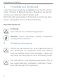
Hinweise zur Anleitung 1 Hinweise zur Anleitung Lesen Sie diese Anleitung sorgfältig, bevor Sie Ihr Homematic IP Gerät in Betrieb nehmen. Bewahren Sie die Anleitung zum späteren Nachschlagen auf! Wenn Sie das Gerät anderen Personen zur Nutzung überlassen, übergeben Sie auch diese Anleitung. Benutzte Symbole: Achtung! Hier wird auf eine Gefahr hingewiesen. Hinweis. Dieser Abschnitt enthält zusätzliche wichtige Informationen. 2 Gefahrenhinweise Öffnen Sie das Gerät nicht.
Gefahrenhinweise Verwenden Sie das Gerät nicht, wenn es von außen erkennbare Schäden, z. B. am Gehäuse, an Bedienelementen oder an den Anschlussbuchsen ausweist. Lassen Sie das Gerät im Zweifelsfall von einer Fachkraft prüfen. Betreiben Sie das Gerät nur in trockener sowie staubfreier Umgebung, setzen Sie es keinem Einfluss von Feuchtigkeit, Vibrationen, ständiger Sonnen- oder anderer Wärmeeinstrahlung, Kälte und keinen mechanischen Belastungen aus.
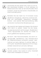
Gefahrenhinweise Der Aktor ist Teil der Gebäudeinstallation. Bei der Planung und Errichtung sind die einschlägigen Normen und Richtlinien des Landes zu beachten. Der Betrieb des Gerätes ist ausschließlich am 230 V/50 Hz-Wechselspannungsnetz zulässig. Arbeiten am 230-V-Netz dürfen nur von einer Elektrofachkraft (nach VDE 0100) erfolgen. Dabei sind die geltenden Unfallverhütungsvorschriften zu beachten.
Gefahrenhinweise Eine Überlastung kann zur Zerstörung des Gerätes, zu einem Brand oder zu einem elektrischen Schlag führen. Der Stromkreis, an dem das Gerät und die Last angeschlossen werden, muss mit einem Leitungsschutzschalter gemäß EN60898-1 (Auslösecharakteristik B oder C, max. 16 A Nennstrom, min. 6 kA Abschaltvermögen, Energiebegrenzungsklasse 3) abgesichert sein. Installationsvorschriften lt. VDE 0100 bzw. HD384 oder IEC 60364 müssen beachtet werden.
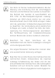
Gefahrenhinweise Fällen die Verwendung von Einschaltstrombegrenzern an den Schaltausgängen. Das Gerät ist nur für den Einsatz in wohnungsähnlichen Umgebungen geeignet. Jeder andere Einsatz, als der in dieser Bedienungsanleitung beschriebene, ist nicht bestimmungsgemäß und führt zu Gewährleistungs- und Haftungsausschluss.
Funktion und Geräteübersicht 3 Funktion und Geräteübersicht Der Homematic IP Schalt-Mess-Aktor (16 A) eignet sich für die Montage in einer Unterputz- oder Aufputzdose. Einmal installiert schaltet er angeschlossene Verbraucher (z. B. Leuchten) ein bzw. aus und misst ihren Energieverbrauch. Der Schalt-Mess-Aktor ermöglicht eine komfortable Steuerung angeschlossener Verbraucher per Funk-Fernbedienung oder über eine Smartphone App.
Allgemeine Systeminformationen 4 Allgemeine Systeminformationen Dieses Gerät ist Teil eines Smart-Home-Systems und kommuniziert über das Homematic IP Funkprotokoll. Alle Geräte des Systems können komfortabel und individuell per Smartphone oder PC konfiguriert werden. Welcher Funktionsumfang sich innerhalb des Systems im Zusammenspiel mit weiteren Komponenten ergibt, entnehmen Sie bitte dem Homematic IP Anwenderhandbuch. Alle technischen Dokumente und Updates finden Sie stets aktuell unter www.eQ-3.de.
Inbetriebnahme Durch eine unsachgemäße Installation gefährden Sie • Ihr eigenes Leben; das Leben der Nutzer der elektrischen Anlage. • Mit einer unsachgemäßen Installation riskieren Sie schwere Sachschäden, z. B. durch Brand. Es droht für Sie die persönliche Haftung bei Personen- und Sachschäden.
Inbetriebnahme Die Installation darf nur in handelsüblichen Schalterdosen (Gerätedosen) gemäß DIN 49073-1 oder Aufputzdosen gemäß DIN 60670-1 (z. B. Abox 025 oder Abox 040) erfolgen. Beachten Sie bei der Installation die Gefahrenhinweise gemäß „2 Gefahrenhinweise“ auf Seite 6. Zugelassene Leitungsquerschnitte zum Anschluss an den Schalt-Mess-Aktor sind: Starre Leitung [mm2] Flexible Leitung ohne Aderendhülse [mm2] 1,5 – 2,50 1,5 – 2,50 5.
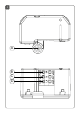
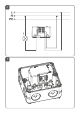
Inbetriebnahme • • • 5.2.2 braucher (s. Abbildung 2). Setzen Sie den Aktor in eine geeignete Unterputzdose. Sie können die Fixieröse (A) bei Bedarf entfernen. Schließen Sie die Unterputzdose mit einer geeigneten Abdeckung. Schalten Sie die Haussicherung wieder ein, um den Anlernmodus des Geräts zu aktivieren (s. „5.3 Anlernen“ auf Seite 16).
Inbetriebnahme 5.3 Anlernen Bitte lesen Sie diesen Abschnitt erst vollständig, bevor Sie mit dem Anlernen beginnen. Richten Sie zunächst Ihren Homematic IP Access Point über die Homematic IP App ein, um weitere Homematic IP Geräte im System nutzen zu können. Ausführliche Informationen dazu finden Sie in der Bedienungsanleitung des Access Points. Sie können das Gerät sowohl an den Access Point als auch an die Homematic Zentrale CCU2 anlernen.
Inbetriebnahme Sollten die 3 Minuten bereits verstrichen sein, schalten Sie die Netzspannung aus und wieder ein, um den Anlernmodus erneut zu starten. • • • • • • • Das Gerät erscheint automatisch in der Homematic IP App. Zur Bestätigung geben Sie in der App die letzten vier Ziffern der Gerätenummer (SGTIN) ein oder scannen Sie den QR-Code. Die Gerätenummer finden Sie auf dem Aufkleber im Lieferumfang oder direkt am Gerät. Warten Sie, bis der Anlernvorgang abgeschlossen ist.
Fehlerbehebung 6 Fehlerbehebung 6.1 Befehl nicht bestätigt Bestätigt mindestens ein Empfänger einen Befehl nicht, leuchtet zum Abschluss der fehlerhaften Übertragung die LED rot auf. Grund für die fehlerhafte Übertragung kann eine Funkstörung sein (s. „8 Allgemeine Hinweise zum Funkbetrieb“ auf Seite 22). Die fehlerhafte Übertragung kann folgende Ursachen haben: • Empfänger nicht erreichbar, • Empfänger kann Befehl nicht ausführen (Lastausfall, mechanische Blockade etc.) oder • Empfänger defekt. 6.
Fehlerbehebung vermehrte und funkintensive Anlernprozesse der Fall sein. Eine Überschreitung des Duty Cycle Limits wird durch ein langes rotes Blinken der LED angezeigt und kann sich durch temporär fehlende Funktion des Gerätes äußern. Nach kurzer Zeit (max. 1 Stunde) ist die Funktion des Gerätes wiederhergestellt. 6.3 Fehlercodes und Blinkfolgen Blinkcode Bedeutung Lösung Kurzes oranges Blinken Funkübertra- Warten Sie, bis die gung/ Übertragung beenSendeverdet ist.
Fehlerbehebung Kurzes oranges Blinken (alle 10 s) Anlernmodus aktiv Geben Sie die letzten vier Ziffern der GeräteSeriennummer zur Bestätigung ein (s. „5.3 Anlernen“ auf Seite 16). 1x langes rotes Leuchten Vorgang fehlgeschlagen oder DutyCycle-Limit erreicht Versuchen Sie es erneut („6.1 Befehl nicht bestätigt“ auf Seite 18 oder „6.2 Duty Cycle“ auf Seite 18). 6x langes rotes Blinken Gerät defekt Achten Sie auf die Anzeige in Ihrer App oder wenden Sie sich an Ihren Fachhändler.
Wartung und Reinigung 7 Wartung und Reinigung Das Gerät ist wartungsfrei. Überlassen Sie eine Wartung oder Reparatur einer Fachkraft. Vor Ausbau des Gerätes unbedingt Netzspannung freischalten (Sicherungsautomat abschalten)! Arbeiten am 230 V-Netz dürfen nur von einer Elektro-Fachkraft (nach VDE 0100) erfolgen. Reinigen Sie das Gerät mit einem weichen, sauberen, trockenen und fusselfreien Tuch. Für die Entfernung von stärkeren Verschmutzungen kann das Tuch leicht mit lauwarmem Wasser angefeuchtet werden.
Allgemeine Hinweise zum Funkbetrieb 8 Allgemeine Hinweise zum Funkbetrieb Die Funk-Übertragung wird auf einem nicht exklusiven Übertragungsweg realisiert, weshalb Störungen nicht ausgeschlossen werden können. Weitere Störeinflüsse können hervorgerufen werden durch Schaltvorgänge, Elektromotoren oder defekte Elektrogeräte. Die Reichweite in Gebäuden kann stark von der im Freifeld abweichen.
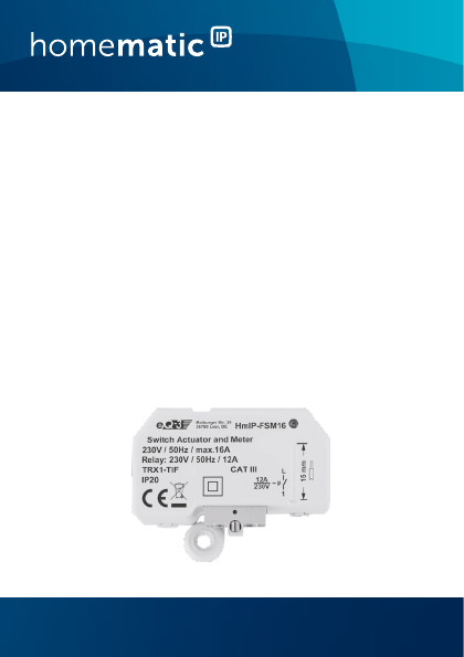
Technische Daten 9 Technische Daten Geräte-Kurzbezeichnung: HmIP-FSM16 Versorgungsspannung: 230 V/50 Hz 16 A max. Stromaufnahme: Leistungsaufnahme Ruhebetrieb: 0,2 W 2760 W dauerhaft Max. Schaltleistung: 3680 W für 20 min Max.
Technische Daten Technische Änderungen vorbehalten. Entsorgungshinweis Gerät nicht im Hausmüll entsorgen! Elektronische Geräte sind entsprechend der Richtlinie über Elektro- und Elektronik-Altgeräte über die örtlichen Sammelstellen für Elektronik-Altgeräte zu entsorgen. Konformitätshinweis Das CE-Zeichen ist ein Freiverkehrszeichen, das sich ausschließlich an die Behörden wendet und keine Zusicherung von Eigenschaften beinhaltet. Bei technischen Fragen zum Gerät wenden Sie sich bitte an Ihren Fachhändler.
Technische Daten Package contents Quantity Description 1 Homematic IP Switch Actuator and Meter (16 A) – flush-mount 1 Operating manual Documentation © 2016 eQ-3 AG, Germany. All rights reserved. This manual may not be reproduced in any format, either in whole or in part, nor may it be duplicated or edited by electronic, mechanical or chemical means, without the written consent of the publisher. Typographical and printing errors cannot be excluded.
Technische Daten Table of contents 1 2 3 4 5 Information about this manual....................................27 Hazard information.........................................................27 Function and device overview..................................... 31 General system information.........................................32 Start-up.............................................................................33 5.1 5.2 5.3 6 Troubleshooting............................................................
Information about this manual 1 Information about this manual Please read this manual carefully before beginning operation with your Homematic IP component. Keep the manual so you can refer to it at a later date if you need to. If you hand over the device to other persons for use, please hand over this manual as well. Symbols used: Attention! This indicates a hazard. Please note: This section contains important additional information. 2 Hazard information Do not open the device.
Hazard information Do not use the device if there are signs of damage to the housing, control elements or connecting sockets, for example. If you have any doubts, have the device checked by an expert. The device may only be operated in dry and dustfree environment and must be protected from the effects of moisture, vibrations, solar or other methods of heat radiation, cold and mechanical loads. The device is not a toy; do not allow children to play with it. Do not leave packaging material lying around.
Hazard information The actuator is part of the building installation. The relevant national standards and directives must be taken into consideration during planning and set-up. The device has been designed solely for operation on a 230 V/50 Hz AC supply. Only qualified electricians (to VDE 0100) are permitted to carry out work on the 230 V mains. Applicable accident prevention regulations must be complied with whilst such work is being carried out.
Hazard information Exceeding this capacity could lead to the destruction of the device, fires or electric shocks. The circuit to the which the device and the load will be connected has to be secured by a cable protection switch in accordance with EN60898-1 (tripping characteristic B or C, max. 16 A rated current, min. 6 kA interrupting rating, energy limiting class 3). Installation regulations according to VDE 0100 and HD382 or 60364 have to be considered.
Function and device overview The device may only be operated within residential buildings. Using the device for any purpose other than that described in this operating manual does not fall within the scope of intended use and shall invalidate any warranty or liability. 3 Function and device overview The Homematic IP Switch Actuator and Meter (16 A) offers installation with a flush-mounting or surfacemounting box. Once installed, the device switches connected loads (e.g.
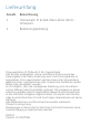
General system information Device overview (see figure 1): (A) (B) (C) (D) 4 Fixing lug Connecting terminal 1 (switched phase) Connecting terminal N (neutral conductor) Connecting terminal L (phase conductor) General system information This device is part of a smart home system and works with the Homematic IP radio protocol. All devices of the system can be configured comfortably and individually with a smartphone or PC.
Start-up 5 5.1 Start-up Installation instructions Please read this entire section before starting to install the device. Before installation, please note the device number (SGTIN) labelled on the device as well as the exact installation location in order to make later allocation easier. You can also find the device number on the QR code sticker supplied.
Start-up *Specialist knowledge required for installation: The following specialist knowledge is particularly important during installation: • The “5 safety rules” to be used: Disconnect from mains; Safeguard from switching on again; Check that system is deenergised; Earth and short circuit; Cover or cordon off neighbouring live parts; • Select suitable tool, measuring equipment and, if necessary, personal safety equipment; • Evaluation of measuring results; • Selection of electrical installation material f
Start-up Permitted cable cross sections for connecting to the switch actuator and meter are: rigid cable [mm2] flexible cable without ferrule [mm2] 1.5 – 2.50 1.5 – 2.50 5.2 Installation You can install the switch actuator and meter • in a flush-mounting box or • in a surface-mounting box . 5.2.1 Flush-mounting box installation To install the switch actuator and meter in a flush-mounting box, please proceed as follows: • Switch off the fuse of the power circuit.
Start-up 5.2.2 Surface-mounting box installation To install the switch actuator and meter in a surfacemounting box, please proceed as follows: • Switch off the fuse of the power circuit. • Connect the actuator to L (D) and N (C) to obtain power supply (see fig. 2). • Route the switched phase (B) to the consumer (see fig. 2). • Fix the actuator to an appropriate surfacemounting box (e.g. Abox 025 or Abox 040) (see figure 3). • Fix the actuator to the holding mandrel using the fixing lug.
Start-up You can connect the device either to the Access Point or to the Homematic Central Control Unit CCU2. For detailed information, please refer to the Homematic IP User Guide, available for download in the download area of www.eQ-3.de. To integrate the switch actuator and meter into your system and enable it to communicate with other Homematic IP devices, you must teach-in the device to your Homematic IP Access Point first.
Troubleshooting • • • • • plied or attached to the device. Please wait until teach-in is completed. If teaching-in was successful, the LED lights up green. The device is now ready for use. If the LED lights up red, please try again. Select the desired solution for your device. In the app, give the device a name and allocate it to a room. 6 Troubleshooting 6.
Troubleshooting 6.2 Duty cycle The duty cycle is a legally regulated limit of the transmission time of devices in the 868 MHz range. The aim of this regulation is to safeguard the operation of all devices working in the 868 MHz range. In the 868 MHz frequency range we use, the maximum transmission time of any device is 1% of an hour (i.e. 36 seconds in an hour). Devices must cease transmission when they reach the 1% limit until this time restriction comes to an end.
Troubleshooting 6.3 Error codes and flashing sequences Flashing code Meaning Solution Short orange flashing Radio transmission/ attempting to transmit/data transmission Wait until the transmission is completed. 1x long green lighting Transmission confirmed You can continue operation. 1x long red lighting Transmission failed Please try again (s. „6.1 Command not confirmed“ on page 38).
Maintenance and cleaning 6x long red flashing Device defective Please see your app for error message or contact your retailer. 1x orange and 1 x green lighting Test display Once the test display has stopped, you can continue. 7 Maintenance and cleaning The product does not require any maintenance. Enlist the help of an expert to carry out any maintenance or repairs. The mains voltage must be disconnected before the device is removed (trip the miniature circuitbreaker).
General information about radio operation 8 General information about radio operation Radio transmission is performed on a non-exclusive transmission path, which means that there is a possibility of interference occurring. Interference can also be caused by switching operations, electrical motors or defective electrical devices. The range of transmission within buildings can differ greatly from that available in the open air.
Technical specifications 9 Technical specifications Device short description: Supply voltage: Current consumption: Standby power consumption: Max. switching capacity: HmIP-FSM16 230 V/50 Hz 16 A max. 0.2 W 2760 W permanent 3680 W for 20 minutes Max. switching current: 12 A permanent 16 A for 20 minutes Kind of load: ohmic load, cosφ≥0.95 Relay: NO contact, 1-pole, µ contact Cable type and cross section: rigid and flexible cable, 1.5 - 2.
Technical specifications Receiver category: Typ. open area RF range: Duty cycle: SRD category 2 180 m < 1 % per h/< 10 % per h Subject to technical changes. Instructions for disposal Do not dispose of the device with regular domestic waste! Electronic equipment must be disposed of at local collection points for waste electronic equipment in compliance with the Waste Electrical and Electronic Equipment Directive.
Kostenloser Download der Homematic IP App! Free download of the Homematic IP app! Bevollmächtigter des Herstellers: Manufacturer’s authorised representative: eQ-3 AG Maiburger Straße 29 26789 Leer / GERMANY www.eQ-3.