Inhaltsverzeichnis 1 2 3 4 5 6 Hinweise zur Anleitung....................................................2 Gefahrenhinweise.............................................................2 Funktion und Geräteübersicht.......................................6 Allgemeine Systeminformationen................................. 7 Adapter für Markenschalter............................................8 Inbetriebnahme............................................................... 12 6.1 6.2 6.
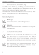
Hinweise zur Anleitung 1 Hinweise zur Anleitung Lesen Sie diese Anleitung sorgfältig, bevor Sie Ihr Homematic IP Gerät in Betrieb nehmen. Bewahren Sie die Anleitung zum späteren Nachschlagen auf! Wenn Sie das Gerät anderen Personen zur Nutzung überlassen, übergeben Sie auch diese Anleitung. Benutzte Symbole: Achtung! Hier wird auf eine Gefahr hingewiesen. Hinweis. Dieser Abschnitt enthält zusätzliche wichtige Informationen! 2 Gefahrenhinweise Öffnen Sie das Gerät nicht.
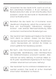
Gefahrenhinweise Verwenden Sie das Gerät nicht, wenn es von außen erkennbare Schäden, z. B. am Gehäuse, an Bedienelementen oder an den Anschlussbuchsen ausweist. Lassen Sie das Gerät im Zweifelsfall von einer Fachkraft prüfen. Betreiben Sie das Gerät nur in trockener sowie staubfreier Umgebung, setzen Sie es keinem Einfluss von Feuchtigkeit, Vibrationen, ständiger Sonnen- oder anderer Wärmeeinstrahlung, Kälte und keinen mechanischen Belastungen aus.
Gefahrenhinweise Der Aktor ist Teil der Gebäudeinstallation. Bei der Planung und Errichtung sind die einschlägigen Normen und Richtlinien des Landes zu beachten. Der Betrieb des Gerätes ist ausschließlich am 230 V/50 Hz-Wechselspannungsnetz zulässig. Arbeiten am 230 V-Netz dürfen nur von einer Elektrofachkraft (nach VDE 0100) erfolgen. Dabei sind die geltenden Unfallverhütungsvorschriften zu beachten.
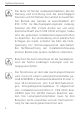
Gefahrenhinweise Vor dem Anschließen des Aktors muss die Sicherung im Sicherungskasten herausgenommen werden. Das Gerät darf, ausgenommen zur Konfiguration, nur mit der dazugehörigen Schalterabdeckung betrieben werden. Das Gerät ist nur für den Einsatz in wohnungsähnlichen Umgebungen geeignet. Jeder andere Einsatz, als der in dieser Bedienungsanleitung beschriebene, ist nicht bestimmungsgemäß und führt zu Gewährleistungs- und Haftungsausschluss.
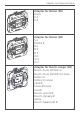
Funktion und Geräteübersicht 3 Funktion und Geräteübersicht Der Homematic IP Wandtaster für Markenschalter ermöglicht die Steuerung von anderen Homematic IP Geräten und Funktionen über eine Tasterwippe. Mit nur einem Tastendruck ist es möglich, beispielsweise die Heizung in den Ecobetrieb zu versetzen, Licht ein- und auszuschalten oder im Rahmen von Sicherheitsfunktionen das Panik-Licht zu schalten.
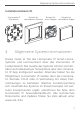
Allgemeine Systeminformationen Installationsübersicht Homematic IP Wandtaster 4 Beispiel für Beispiel für Beispiel für vorhandenen Rahmen einen Adapter vorhandene Wippe Allgemeine Systeminformationen Dieses Gerät ist Teil des Homematic IP Smart-HomeSystems und kommuniziert über das Homematic IP Funkprotokoll. Alle Geräte des Systems können komfortabel und individuell per Smartphone über die Homematic IP App konfiguriert werden.
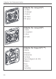
Adapter für Markenschalter 5 Adapter für Markenschalter Um eine Kompatibilität mit möglichst vielen Herstellern zu erreichen und eine Integration in die verschiedenen Designs zu erleichtern, sind die nachfolgenden Wippadapter als Zubehör erhältlich. In Ausnahmefällen kann eine Anpassung der Wippenhalterungen oder Rahmen der verschiedenen Hersteller durch Sägen oder Feilen erforderlich sein. *) Anpassen der Wippenhalterungen erforderlich. **) Anpassen der Rahmen erforderlich.
Adapter für Markenschalter Adapter für Berker (B1) Arsys K.1 K.5 Adapter für Berker (B2) S.1 Modul 2 B.1 B.3 B.7 Q.1 Q.3 Q.
Adapter für Markenschalter Adapter für Jung (J1)*) LS 990 LS design LS plus CD 500 CD plus Adapter für Jung (J2)*) A 500 A creation A plus AS 500 Adapter für Kopp (K)*) **) Alaska Athenis Ambiente Europa Paris (Objekt HK 05) Milano Rivo Cadiz Venedig 10
Adapter für Markenschalter Adapter für Gira (GD) Standard Adapter für Gira 55 (G) Standard 55 E2 Event E22 ClassiX E3 Esprit Adapter für düwi / Popp (D)**) Architaste Arcada Trend Standard Quadro (Plus2000) EverLuxe (Forever) ProLuxe (Quadro) PrimaLuxe Eco 11
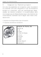
Inbetriebnahme 6 6.1 Inbetriebnahme Installationshinweise Bitte lesen Sie diesen Abschnitt erst vollständig, bevor Sie mit der Installation beginnen. Bitte notieren Sie sich vor der Installation die auf dem Gerät angebrachte Gerätenummer (SGTIN) und den Installationsort, damit Sie das Gerät im Nachhinein leichter zuordnen können. Alternativ steht die Gerätenummer auch auf dem beiliegenden QR-Code-Aufkleber.
Inbetriebnahme *Erforderliche Fachkenntnisse für die Installation: Für die Installation sind insbesondere folgende Fachkenntnisse erforderlich: • Die anzuwendenden „5 Sicherheitsregeln“: Freischalten; gegen Wiedereinschalten sichern; Spannungsfreiheit feststellen; Erden und Kurzschließen; benachbarte, unter Spannung stehende Teile abdecken oder abschranken; • Auswahl des geeigneten Werkzeuges, der Messgeräte und ggf.
Inbetriebnahme Zugelassene Leitungsquerschnitte zum Anschluss an den Wandtaster sind: Starre Leitung [mm2] Flexible Leitung mit und ohne Aderendhülse [mm2] 0,75 – 1,50 0,75 – 1,50 6.2 Installation Für die Installation des Wandtasters gehen Sie wie folgt vor: Schritt 1 Schalten Sie die Leitungsschutzschalter des Stromkreises ab. Schritt 2 Ziehen Sie gegebenenfalls die Wippe vom Rahmen des entsprechenden Schalters ab. Ziehen Sie anschließend den Rahmen mitsamt Klemm-/Haltestück vom Schalter ab.
Inbetriebnahme Schritt 4 Lösen Sie die Verdrahtung und entfernen Sie ggf. den vorhandenen Schalter. Schritt 5 Schließen Sie den Außenleiter an die Anschlussklemme L (B) an (s. Abbildung 2). Schritt 6 Schließen Sie den Neutralleiter an die Anschlussklemme N (C) an (s. Abbildung 2). Schritt 7 Befestigen Sie den Wandtaster mittels der mitgelieferten Schrauben an der Unterputzdose. Bitte beachten Sie bei der Montage, dass sich die Systemtaste (A) des Aktors links oben befinden muss.
Inbetriebnahme 6.3 Anlernen Bitte lesen Sie diesen Abschnitt erst vollständig, bevor Sie mit dem Anlernen beginnen. Richten Sie zunächst Ihren Homematic IP Access Point über die Homematic IP App ein, um weitere Homematic IP Geräte im System nutzen zu können. Ausführliche Informationen dazu finden Sie in der Bedienungsanleitung des Access Points. Sie können das Gerät sowohl an den Access Point als auch an die Homematic Zentrale CCU2 anlernen.
Inbetriebnahme Sollte die Zeit bereits verstrichen sein, können Sie den Anlernmodus manuell für weitere 3 Minuten starten, indem Sie die Wippe entfernen und die Systemtaste (A) kurz drücken (s. Abbildung 5). • • • • • • • Das Gerät erscheint automatisch in der Homematic IP App. Zur Bestätigung geben Sie in der App die letzten vier Ziffern der Gerätenummer (SGTIN) ein oder scannen Sie den QR-Code. Die Gerätenummer finden Sie auf dem Aufkleber im Lieferumfang oder direkt am Gerät.
Fehlerbehebung 7 Fehlerbehebung 7.1 Befehl nicht bestätigt Bestätigt mindestens ein Empfänger einen Befehl nicht, leuchtet zum Abschluss der fehlerhaften Übertragung die LED (A) rot auf. Grund für die fehlerhafte Übertragung kann eine Funkstörung sein (s. „10 Allgemeine Hinweise zum Funkbetrieb“ auf Seite 22). Die fehlerhafte Übertragung kann außerdem folgende Ursachen haben: • Empfänger nicht erreichbar, • Empfänger kann Befehl nicht ausführen (Lastausfall, mechanische Blockade etc.
Fehlerbehebung vermehrte und funkintensive Anlernprozesse der Fall sein. Eine Überschreitung des Duty Cycle Limits wird durch ein langes rotes Leuchten der LED (A) angezeigt und kann sich durch temporär fehlende Funktion des Gerätes äußern. Nach kurzer Zeit (max. 1 Stunde) ist die Funktion des Gerätes wiederhergestellt. 7.3 Fehlercodes und Blinkfolgen Blinkcode Bedeutung Lösung Kurzes oranges Blinken Funkübertra- Warten Sie, bis die gung/SenÜbertragung beendeversuch/ det ist.
Fehlerbehebung Kurzes oranges Blinken (alle 10 s) Anlernmodus aktiv Geben Sie die letzten vier Ziffern der Geräte-Seriennummer zur Bestätigung ein (s. „6.3 Anlernen“ auf Seite 16). 6x langes rotes Blinken Gerät defekt Achten Sie auf die Anzeige in Ihrer App oder wenden Sie sich an Ihren Fachhändler. 1x oranges und 1x grünes Leuchten Testanzeige Nachdem die Testanzeige erloschen ist, können Sie fortfahren.
Wiederherstellung der Werkseinstellungen 8 Wiederherstellung der Werkseinstellungen Die Werkseinstellungen des Gerätes können wiederhergestellt werden. Dabei gehen alle Einstellungen verloren. Um die Werkseinstellungen des Wandtasters wiederherzustellen, gehen Sie wie folgt vor: • Entfernen Sie ggf. die Wippe (s. Abbildung 4). • Drücken Sie für 4 s mit einem spitzen Gegenstand (z. B. mit einem Stift) auf die Systemtaste (A), bis die LED (A) schnell orange zu blinken beginnt (s. Abbildung 5).
Wartung und Reinigung 9 Wartung und Reinigung Das Gerät ist wartungsfrei. Überlassen Sie eine Wartung oder Reparatur einer Fachkraft. Reinigen Sie das Gerät mit einem weichen, sauberen, trockenen und fusselfreien Tuch. Für die Entfernung von stärkeren Verschmutzungen kann das Tuch leicht mit lauwarmem Wasser angefeuchtet werden. Achten Sie darauf, dass keine Feuchtigkeit in das Gerät gelangt.
Technische Daten Hiermit erklärt die eQ-3 AG, Maiburger Str. 29, 26789 Leer, Deutschland, dass der Funkanlagentyp Homematic IP HmIP-BRC2 der Richtlinie 2014/53/EU entspricht. Der vollständige Text der EU-Konformitätserklärung ist unter der folgenden Internetadresse verfügbar: www.eq-3.de 11 Technische Daten Geräte-Kurzbezeichnung: Versorgungsspannung: Stromaufnahme: Leistungsaufnahme Ruhebetrieb: Leitungsart und -querschnitt: HmIP-BRC2 230 V/50 Hz 10 mA max.
Technische Daten Technische Änderungen vorbehalten. Entsorgungshinweis Gerät nicht im Hausmüll entsorgen! Elektronische Geräte sind entsprechend der Richtlinie über Elektro- und Elektronik-Altgeräte über die örtlichen Sammelstellen für Elektronik-Altgeräte zu entsorgen. Konformitätshinweis Das CE-Zeichen ist ein Freiverkehrszeichen, das sich ausschließlich an die Behörden wendet und keine Zusicherung von Eigenschaften beinhaltet. Bei technischen Fragen zum Gerät wenden Sie sich bitte an Ihren Fachhändler.
Package contents Quantity Description 1 Homematic IP Remote Control for brand switches – 2 channels 2 Screws 3,2 x 15 mm 2 Screws 3,2 x 25 mm 1 Operating manual Documentation © 2018 eQ-3 AG, Germany All rights reserved. Translation from the original version in German. This manual may not be reproduced in any format, either in whole or in part, nor may it be duplicated or edited by electronic, mechanical or chemical means, without the written consent of the publisher.
Table of contents 1 2 3 4 5 6 Information about this manual....................................27 Hazard information.........................................................27 Function and device overview.................................... 30 General system information.........................................32 Adapters for brand switch systems.............................32 Start-up.............................................................................36 6.1 6.2 6.3 7 Troubleshooting..........
Information about this manual 1 Information about this manual Please read this manual carefully before beginning operation with your Homematic IP component. Keep the manual so you can refer to it at a later date if you need to. If you hand over the device to other persons for use, please hand over this manual as well. Symbols used: Attention! This indicates a hazard. Please note: This section contains important additional information. 2 Hazard information Do not open the device.
Hazard information Do not use the device if there are signs of damage to the housing, control elements or connecting sockets, for example. If you have any doubts, have the device checked by an expert. The device may only be operated in dry and dustfree environment and must be protected from the effects of moisture, vibrations, solar or other methods of heat radiation, cold and mechanical loads. The device is not a toy; do not allow children to play with it. Do not leave packaging material lying around.
Hazard information The actuator is part of the building installation. The relevant national standards and directives must be taken into consideration during planning and set-up. The device has been designed solely for operation on a 230 V/50 Hz AC supply. Only qualified electricians (to VDE 0100) are permitted to carry out work on the 230 V mains. Applicable accident prevention regulations must be complied with whilst such work is being carried out.
Function and device overview Before the actuator is connected, remove the fuse from the fuse box. Except for configuration, the device may only be operated with an associated switch cover. The device may only be operated within residential buildings. Using the device for any purpose other than that described in this operating manual does not fall within the scope of intended use and shall invalidate any warranty or liability.
Function and device overview Adapters for different switches allow you to replace switches made by popular manufacturers in a cost-effective way. Using the components of existing or planned switches and cabling reduces the installation costs to a minimum. The design, colour and finish of switches that have already been installed does not change, since the existing frames and rockers can continue to be used. Device overview (see fig.
General system information 4 General system information This device is part of the Homematic IP smart home system and works with the Homematic IP radio protocol. All devices of the system can be configured comfortably and individually with the Homematic IP smartphone app. Alternatively, you can operate the Homematic IP devices via the Homematic Central Control Unit CCU2 or in connection with various partner solutions.
Adapters for brand switch systems Adapter for Merten (M) Atelier M 1-M M-Plan M-Plan Echtglas M-Pure M-Smart M-ARC M-Star Atelier-Basis*) M1 Basis*) Adapter for Berker (B1) Arsys K.1 K.5 Adapter for Berker (B2) S.1 Modul 2 B.1 B.3 B.7 Q.1 Q.3 Q.
Adapters for brand switch systems Adapter for Busch-Jaeger (BJ) Busch-Duro 2000® SI Busch-Duro 2000® SI Linear Reflex SI Reflex SI Linear carat® future® linear solo® Busch-axcent® Busch-dynasty® alpha Busch-balance® SI Adapter for Jung (J1)*) LS 990 LS design LS plus CD 500 CD plus Adapter for Jung (J2)*) A 500 A creation A plus AS 500 34
Adapters for brand switch systems Adapter for Kopp (K)*) **) Alaska Athenis Ambiente Europa Paris (Objekt HK 05) Milano Rivo Cadiz Venedig Adapter for Gira (GD) Standard Adapter for Gira 55 (G) Standard 55 E2 Event E22 ClassiX E3 Esprit 35
Start-up Adapter for düwi / Popp (D)**) Architaste Arcada Trend Standard Quadro (Plus2000) EverLuxe (Forever) ProLuxe (Quadro) PrimaLuxe Eco 6 Start-up 6.1 Installation instructions Please read this entire section before starting to install the device. Before installation, please note the device number (SGTIN) labelled on the device as well as the exact installation location in order to make later allocation easier. You can also find the device number on the QR code sticker supplied.
Start-up Incorrect installation can put • your own life at risk; • and the lives of other users of the electrical system. Incorrect installation also means that you are running the risk of serious damage to property, e.g. because of a fire. You may be personally liable in the event of injuries or damage to property.
Start-up Installation may only take place in normal commercial switch boxes (device boxes) in accordance with DIN 49073-1. The device may only be operated with adapters and an associated, fitted switch cover. The switch cover may only be removed during configuration. Please observe the hazard information in section “2 Hazard information” on page 27 during installation.
Start-up Step 2 If necessary, pull the rocker off the frame of the relevant switch. Then pull the frame off the switch together with the clamping/retaining piece. The clamping/ retaining piece can be transparent, grey or black depending on the manufacturer, and holds the frame onto the switch. To make removal easier, a flat, pointed object such as a slotted screwdriver can be used. Step 3 Loosen the fastening of the existing switch and carefully remove it from the flush-mounted box.
Start-up Step 9 Now secure the rocker with the adapter in the frame on the actuator. Position the adapter so that both latching lugs fit into the existing elongated holes (see fig. 6). Step 10 Switch the circuit breaker of the power circuit back on again. Step 11 Now, the wall-mount remote control can be connected to the Homematic IP Access Point (see “11.1 Teaching-in” on page 40). 6.3 Teaching-in Please read this entire section before starting the teach-in procedure.
Start-up To integrate the wall-mount remote control into your system and enable it to communicate with other Homematic IP devices, you must connect the device to your Homematic IP Access Point first. To teach-in the wall-mount remote control, please proceed as follows: • Open the Homematic IP app on your smartphone. • Select the menu item “Teach-in device”. • After installation, the teach-in mode remains activated for 3 minutes.
Troubleshooting • • Please select, in which application (e.g. light and/ or security) you would like to use the device. In the app, give the device a name and allocate it to a room. 7 Troubleshooting 7.1 Command not confirmed If at least one receiver does not confirm a command, the device LED (A) lights up red at the end of the failed transmission process. The failed transmission may be caused by radio interference (see “10 General information about radio operation” on page 46).
Troubleshooting comes to an end. Homematic IP devices are designed and produced with 100% conformity to this regulation. During normal operation, the duty cycle is not usually reached. However, repeated and radio-intensive teachin processes mean that it may be reached in isolated instances during start-up or initial installation of a system. If the duty cycle is exceeded, this is indicated by one long red lighting of the device LED (A), and may manifest itself in the device temporarily working incorrectly.
Restore factory settings 1x long red lighting Transmission failed or duty cycle limit is reached Please try again (see sec. “7.1 Command not confirmed” on page 42 or “7.2 Duty cycle” on page 42). Short orange flashing (every 10 s) Teach-in mode active Please enter the last four numbers of the device serial number to confirm (see “6.3 Teaching-in” on page 40). 6x long red flashing Device defective Please see your app for error message or contact your retailer.
Maintenance and cleaning To restore the factory settings of the wall-mount remote control, please proceed as follows: • Remove the rocker if required (see fig. 4). • Press and hold down the system button (A) for 4 seconds with a pointed object (e.g. a pen) until the LED (A) starts flashing orange quickly (see fig. 5). • Release the system button again. • Press and hold down the system button again for 4 seconds, until the LED lights up green. • Release the system button to finish the procedure.
General information about radio operation 10 General information about radio operation Radio transmission is performed on a non-exclusive transmission path, which means that there is a possibility of interference occurring. Interference can also be caused by switching operations, electrical motors or defective electrical devices. The range of transmission within buildings can differ greatly from that available in the open air.
Technical specifications 11 Technical specifications Device short description: HmIP-BRC2 Supply voltage: 230 V/50 Hz Current consumption: 10 mA max. Standby power consumption: 0.2 W Cable type and cross section: rigid and flexible cable, 0.75-1.5 mm² Installation: only in normal commercial switch boxes in accordance with DIN 49073-1 Degree of protection: IP20 Ambient temperature: 5 to 35 °C Dimensions (W x H x D): 71 x 71 x 37 mm Weight: 47 g Radio frequency band: 868.0-868.6 MHz 869.4-869.
Technical specifications Instructions for disposal Do not dispose of the device with regular domestic waste! Electronic equipment must be disposed of at local collection points for waste electronic equipment in compliance with the Waste Electrical and Electronic Equipment Directive. Information about conformity The CE sign is a free trading sign addressed exclusively to the authorities and does not include any warranty of any properties. For technical support, please contact your retailer.