Assembly Instructions Instrucciones de Ensamblaje 120mns SAVE THESE INSTRUCTIONS GUARDE ESTAS INSTRUCCIONES L Shaped Desk with Drawers Escritorio en forma de L con cajones C1930002 Do Not Return! No Vuelvas! Email or call customer service for help first. Envie correo electrónico o llame al servicio para obtener ayuda primero. 1-214-758-1098/Toll free: 1-883-907-1099 Monday-Friday 9am - 4pm CST customer@legacyhfd.
WARNING This product can expose you to chemicals including Formaldehyde, which is known to the State of California to cause cancer or birth defects or other reproductive harm. For more information go to www.P65Warnings.ca.gov/furniture ADVERTENCIA Este producto puede exponerlo a sustancias quím icas, incluyendo el formaldehído, el cual es conocido en el estado de California como causante de cáncer, defectos de nacimiento u otros daños reproductivos. Para obtener más información vaya a www.P65Warnings.ca.
Helpful advice 1. Follow the assembly instructions carefully. 2. Check to ensure all parts, fasteners and hardware are present. 3. To prevent product damage, assemble the furniture on top of the carton. 4. Clean surface of furniture with a duster or damp cloth only. Do not use abrasive cleaners. Consejos útiles 1. Siga a tentamente las instrucciones de montaje. 2. Asegúrese de que la caja contiene todas las piezas, sujeciones y materiales. 3. Monte el mueble sobre la caja para evitar dañarlo. 4.
Parts list/Lista de piezas ITEM DESCRIPTION DESCRIPCIÓN QUANTITY 19 Drawer bottom Tablero inferior de cajón 2 20 Upper drawer front Tablero frontal del cajón superior 1 21 Lower drawer side left Tablero izquierdo del cajón inferior 1 22 Lower drawer side right Tablero derecho del cajón inferior 1 23 Lower drawer back Tablero posterior del cajón inferior 1 24 Lower drawer front Tablero frontal del cajón inferior 1 02
Hardware/Lista de materiales ITEM DESCRIPTION DESCRIPCIÓN QUANTITY A Wood dowel Perno Madera 36 B Cam bolt Perno Metálico 35 C Cam lock Bloqueo metálico 35 Φ3.5×12 mm Tornillo 24 D IMAGE Φ3.5×12 mm Screw E Left glide Planeador izquierdo 2 F Right glide Planeador derecho 2 G Drawer connector (small) Conector de plástico (pequeño) 2 H Φ3.5×12 mm Screw Φ3.5×12 mm Tornillo 8 I Φ4.7×12.5 mm Screw Φ4.7×12.5 mm Tornillo 6 J Φ3.8×35 mm Screw Φ3.
Hardware/Lista de materiales ITEM IMAGE DESCRIPTION DESCRIPCIÓN QUANTITY M Handle Tirador 2 N Plastic file hanger Perchero de plástico 2 O Φ5×50 mm Screw Φ5×50 mm Tornillo 7 P Φ4×14 mm Screw Φ4×14 mm Tornillo 8 Q Metal plate Hoja de hierro 2 R Plastic hole cap pasa cables 1 Note/Nota El uso del tornillo incorrecto puede provocar daños al producto. Antes de iniciar la operación de Using the wrong screw will cause damage.
Necessary tools/Herramientas necesarias Glue Glue not enclosed (We recommend to apply some glue into holes before inserting wood dowels.) Colle non fournie (Nous vous recommandons d’appliquer quelques gouttes de colle dans les trous avant notd’y included ( Weles recommend apply some glue into holes before inserting wood dowels .) introduire chevilles detobois.) Cola, nomadera.) incluida (Le recomendamos colocarunas gotas de cola en los orificios antes de insertar las clavijas de madera.
Attention: In order to help your assembly, do not lock the screw tightly until you have assembled all the other parts. Atención: Con el fin de facilitar su montaje, no apretar el tornillo firmemente hasta que haya ensamblad o todas las otras partes. Step 1/Paso 1 Insert 4 wood dowels (A) into the holes on the edge of left fixed shelf (4). Inserte 4 Pernos maderas (A) en el Estante (4). A Ax4 Step 2/Paso 2 Insert 2 wood dowels (A) into the holes on the edge of bottom back rail (5).
Step 3/Paso 3 Insert 2 wood dowels (A) into the holes on the edge of bottom front rail (6). Insert 2 cam bolts (B) into front rail (7). Inserte 2 Pernos maderas (A) y 2 Pernos metálicos (B) en las Barras (6) (7). A Ax2 B Bx2 Step 4/Paso 4 Insert 2 cam locks (C) into the holes on the bottom front rail (6) to combine with front rail (7). Conecte la Barra (6) a la Barra (7) con 2 Bloqueos metálicos (C).
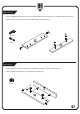
Step 5/Paso 5 Insert 2 wood dowels (A) and 4 cam bolts (B) into gable left (2). Attach 2 left glides (E) to gable left (2) with 6 screws (D). Inserte 2 Pernos maderas (A) y 4 Pernos metálicos (B) en el Marco izquierdo (2). Bloquee 2 Planeadores izquierdos (E) al Marco izquierdo (2) con 6 Tornillos (D). Ax2 B D D Bx4 Dx6 E Ex2 A Step 6/Paso 6 Insert 4 cam locks (C) into left fixed shelf (4), bottom back rail (5) and bottom front rail (6) to combine them with gable left (2).
Step 7/Paso 7 Insert 2 wood dowels (A) and 4 cam bolts (B) into divider (3). Attach 2 right glides (F) to divider (3) with 6 screws. Inserte 2 Pernos maderas (A) y 4 Pernos metálicos (B) en el Marco central (3). Bloquee 2 Planeadores derechos (F) al Marco central (3) con 6 Tornillos (D). Ax2 B D Bx4 F Dx6 Fx2 D A Step 8/Paso 8 Insert 4 cam locks (C) into left fixed shelf (4) and bottom rails (5) (6) to combine them with divider (3).
Step 9/Paso 9 Insert 4 wood dowels (A) into the holes on the edge of left support panel (10). Inserte 4 Pernos maderas (A) en el Tablero soporte (10). Ax4 A Step 10/Paso 10 Insert 2 wood dowels (A) and 3 cam bolts (B) into right support panel (11). Inserte 2 Pernos maderas (A) y 3 Pernos metálicos (B) en el Tablero soporte (11).
Step 11/Paso 11 Insert 3 cam locks (C) into left support panel (10) to combine with right support panel (11). Conecte los Tableros soportes (10) (11) con 3 Bloqueos metálicos (C). Cx3 C Step 12/Paso 12 Insert 6 wood dowels (A) into the holes on the edge of middle back panel (9). Inserte 6 Pernos maderas (A) en el Tablero posterior (9).
Step 13/Paso 13 Connect middle back panel (9) and left support panel (10) with 2 screws (O). Conecte el Tablero posterior (9) al ensamblaje con 2 Tornillos (O). Ox2 O Step 14 /Paso 14 Insert 2 cam bolts (B) into divider(3). Inserte 2 Pernos metálicos (B) en el Marco central (3).
Step 15/Paso 15 Insert 2 cam locks (C) into middle back panel (9) to combine with divider (3). Conecte el Tablero posterior (9) al Marco central (3) con 2 Bloqueos metálicos (C). Cx2 C Step 16/Paso 16 Slide left back panel (8) into the assembly part. Insert 2 cam bolts (B) into right support panel (11). Inserte el Tablero posterior (8) en el ensamblaje. Inserte 2 Pernos metálicos (B) en el tablero soporte (11).
Step 17/Paso 17 Insert 6 wood dowels (A) into right back panel (13). Inserte 6 Pernos maderas (A) en el Tablero posterior derecho (13). Ax6 A Step 18 /Paso 18 Insert 4 wood dowels (A) into the holes on the edge of right fixed shelf (14). Inserte 4 Pernos maderas (A) en el Estante (14).
Step 19/Paso 19 Connect right back panel (13) and right fixed shelf (14) with 3 screws (O). Conecte el Tablero posterior derecho (13) al Estante (14) con 3 Tornillos (O). Ox3 O Step 20/Paso 20 Insert 2 wood dowels (A) and 4 cam bolts (B) into gable right (12). Inserte 2 Pernos maderas (A) y 4 Pernos metálicos (B) en el Marco derecho (12).
Step 21/Paso 21 Insert 4 cam locks (C) to right back panel (13) and right fixed shelf (14) to combine them with gable right (12). Conecte el Marco derecho (12) al Tablero posterior derecho (13) con 4 Bloqueos metálicos (C). Cx4 C Step 22 /Paso 22 Combine left assembly part and right assembly part with 2 cam locks (C) and 2 screws (O) . Conecte el Tablero posterior derecho (13) al ensamblaje con 2 Bloqueos metálicos (C) y 2 Tornillos (O).
Step 23/Paso 23 Insert 10 cam bolts (B) into Long top (1). Inserte 10 Pernos metálicos (B) en el Panel superior largo (1). B x 10 B Step 24/Paso 24 Insert 4 cam bolts (B) into short top (15). Inserte 4 Pernos metálicos (B) en el Panel superior corto(15).
Step 25/Paso 25 Combine top and base with 14 cam locks(C). Connect long top (1) and short top (15) with 2 metal plates, tighten with 8 screws (P). Conecte Panel superior (1) al ensamblaje con 14 Bloqueos metálicos (C).Conecte el Panel superior largo (1) al Panel superior corto (15) con 2 Hojas de hierro (Q), cerrarlos bien con 8 tornillos (P). C x 14 P Q Px8 C Q P Qx2 Step 26 /Paso 26 Insert plastic hole cap (R) into the hole on long top (1).
Step 27/Paso 27 Attach left glide (E) to drawer side left (16) with 3 screws (D). Attach right glide (F) to drawer side right (17) with 3 screws (D). Utilice 3 Tornillos (D) para fijar el Planeador izquierdo (E) en el Tablero izquierdo de cajón (16), Utilice 3 Tornillos (D) para fijar el Planeador derecho (F) en el Tablero derecho de cajón (17). F Dx6 D E D Ex1 Fx1 Step 28/Paso 28 Insert 2 drawer connectors (G) to the drawer sides (16) (17) with 4 screws (H).
Step 29/Paso 29 Slide drawer bottom (19) into upper drawer. Inserte el Tablero inferior de cajón (19) en el ensamblaje. Step 30/Paso 30 Align handle (M) with the holes on the drawer front (20) , secure with 2 bolts (L). Insert drawer front (20) into assembly part with 2 screws (I). Inserte el Tirador (M) en el Tablero frontal de cajón (20) con 2 Tornillos (L). Fije el Tablero frontal de cajón (20) en el ensamblaje con 2 Tornillos (I).
Step 31/Paso 31 Attach left glide (E) to drawer side left (21) with 3 screws (D). Attach right glide (F) to drawer side right (22) with 3 screws (D). Utilice 3 Tornillos (D) para fijar el Planeador izquierdo (E) en el Tablero izquierdo de cajón (21), Utilice 3 Tornillos (D) para fijar el Planeador derecho (F) en el Tablero derecho de cajón (22). F Dx6 Ex1 E D D Fx1 Step 32/Paso 32 Insert 2 drawer connectors (K) to drawer sides (21) (22) with 4 screws (H).
Step 33/Paso 33 Slide drawer bottom (19) into lower drawer. Inserte el Tablero inferior de cajón (19) en el ensamblaje. Step 34/Paso 34 Align handle (M) with the holes on drawer front (24) , secure with 2 bolts (L). Insert drawer front (24) into assembly part with 2 screws (I). Inserte el Tirador (M) en el Tablero frontal de cajón (24) con 2 Tornillos (L) . Fije el Tablero frontal de cajón (24) en el ensamblaje con 4 Tornillos (I) .
Step 35/Paso 35 Put 2 plastic file hangers (N) into the drawer sides of the lower drawer. Fije 2 Percheros de plástico (N) en los Tableros laterales del cajón grande. N Nx2 Step 36/Paso 36 Push 2 drawers to the stand assembly. Inserte los cajones en la mesa.
Maximum weight capacities/Capacidades de carga máxima 45 kg 99 lbs. 45 kg 99 lbs. 5 kg 11 lbs. 10 kg 22 lbs. 10 kg 22 lbs. WARNING Please use your furniture correctly and safely. Improper use can cause safety hazards, or damage to your furniture or household items. -This product is intended to hold maximum weight indicated. Exceeding the maximum weight will result in instability and may cause serious injury.
1 YEAR WARRANTY BASIC WARRANTY: Homestar® furniture is warranted by Homestar Corporation (Homestar) to the original purchaser for a period of one year from the date of purchase, subject to the following conditions and limitations. 1. Install and operate this item in accordance with the Installation and operating instructions provided with the product at all times. Any alteration, willful abuse, accident, or misuse of the product shall nullify this warranty. 2.