5002-941 Kitchen Island IMPORTANT Carefully remove all the parts from the carton and place them individually on a soft cloth to prevent scratches or other damage. Carefully and strictly follow these assembly instructions to ensure a completed product as designed. Do not use power tools above 8 volts to assemble. Part List A. Top Unit 1 pc. B. Leaf Top 1 pc. For assembly see instructions in carton 5002-943. homestyles Customer Service: www.homestylesfurniture.com, servicedesk@homestylesfurniture.
5002-942 Kitchen Island IMPORTANT Carefully remove all the parts from the carton and place them individually on a soft cloth to prevent scratches or other damage. Carefully and strictly follow these assembly instructions to ensure a completed product as designed. Do not use power tools above 8 volts to assemble. Part List E. Middle Panel 1 pc. D. Back Upright 1 pc. C. Back Rail 2 pcs. F. Rail 2 pcs. H. Base 1 pc. G. Shelf 4 pcs. N. Back Panel 2 pcs. Hardware List Hex Wrench 1 pc. Cam Lock 4 pcs.
5002-943 Kitchen Island IMPORTANT Carefully remove all the parts from the carton and place them individually on a soft cloth to prevent scratches or other damage. Carefully and strictly follow these assembly instructions to ensure a completed product as designed. Do not use power tools above 8 volts to assemble. Part List I. Post 1 pc. J. Post 1 pc. K. Post 1 pc. L. Post 1 pc. M. Side Panel 2 pcs. O. Shelf 4 pcs. P. Door 1 pc. Q. Door 1 pc. Cartons 5002-941, 5002-942 are also needed for assembly.
Assembly Instructions 2/6 IMPORTANT Use a soft cloth between these parts and the floor. Do not use power tools above 8 volts to assemble. Do not tighten all the bolts until each part is properly assembled. The unit must be level to work properly. Use the included adjustable levelers to level. Keep Hex Wrench as the bolts may need to be tightened in the future. STEP 1 Insert Cam Lock Screws into pre-drilled holes in Posts (K) and (L), then tighten.
Assembly Instructions 3/6 STEP 3 Attach unit and Middle Panel (E) to Base (H) with Head Cap Bolts. (See Figure 3) Head Cap Bolt E H Figure 3 I M J M STEP 4 Attach Posts (I) and (J) to unit with Head Cap Bolts. Slide Side Panels (M) into position.
Assembly Instructions 4/6 STEP 5 Head Cap Bolt F Attach Rails (F) to unit with Head Cap Bolts. Insert Adjustable Pins into posts and middle panel at desired level. (See Figure 4) F O O O Place Shelves (G) and (O) into position. O G G Figure 4 G G Adjustable Pin Figure 6 Figure 5 STEP 6 P Attach Doors (P) and (Q) to unit by sliding door hinges into post hinges. (See Figure 5) Q Attach Knobs to Doors (P) and (Q) with Machine Screws.
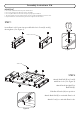
Assembly Instructions 5/6 A STEP 7 Remove drawers from Top Unit (A). Machine Screw Knob STEP 8 Attach Knobs to drawers with Machine Screws. STEP 9 Wood Screw Place Top Unit (A) and Leaf Top (B) upside down on a soft cloth. Attach Top Unit (A) to Leaf Top (B) with Wood Screws into pre-drilled holes.
Assembly Instructions 6/6 Head Cap Bolt STEP 10 Attach top unit to unit with Head Cap Bolts. STEP 11 Slide drawers into position. Level unit by adjusting the adjustable levelers on bottom of unit. (See Figure 8) Note: Unit must be level to work properly.
CARE INSTRUCTIONS NEVER NEVER use glass cleaners on finished furniture. Ammonia chemically attacks the finish. allow liquids to remain on furniture. Absorption causes parts to warp and split and finishes to delaminate. Do not use power tools above 8 volts to assemble. Do not place in direct sunlight. Do not write directly on surface. PREVENT CRACKING PREVENT FADING PREVENT MARKING Do not place hot objects on surface. Do not use rubber based placemats. Do not use commercial waxes and polishes.
5002-89 Bar Stool IMPORTANT Carefully remove all the parts from the carton and place them individually on a soft cloth to prevent scratches or other damage. Carefully and strictly follow these assembly instructions to ensure a completed product as designed. Do not use power tools above 8 volts to assemble. Part List A. Seat 1 pc. B. Leg 1 pc. C. Leg 1 pc. E. Side Stretcher 1 pc. F. Side Stretcher 1 pc. G. Front Stretcher 1 pc. D. Back Frame 1 pc. Hardware List Hex Wrench 1 pc. Flat Washer 11 pcs.
Assembly Instructions 2/3 IMPORTANT Use a soft cloth between these parts and the floor. Do not tighten all the bolts until each part is properly assembled. Keep Hex Wrench as the bolts may need to be tightened in the future. Wood Screw Head Cap Bolt Spring Washer Flat Washer F E G C A B STEP 1 Place Seat (A) upside down on a soft cloth. Attach Legs (B) and (C) to Seat (A) with Flat Washers, Spring Washers and Head Cap Bolts, tightening bolts only halfway.
Assembly Instructions 3/3 Wood Screw Head Cap Bolt (short) Spring Washer Flat Washer Head Cap Bolt (long) Spring Washer Flat Washer D STEP 2 Attach Back Frame (D) to unit with Flat Washers, Spring Washers, Head Cap Bolts (short) and Head Cap Bolts (long), tightening bolts only halfway. (See Figures 3 and 4) Tighten all bolts used in Steps 1 and 2. Insert Wood Screws into pre-drilled holes in unit, then tighten.
CARE INSTRUCTIONS NEVER NEVER use glass cleaners on finished furniture. Ammonia chemically attacks the finish. allow liquids to remain on furniture. Absorption causes parts to warp and split and finishes to delaminate. Do not use power tools above 8 volts to assemble. Do not place in direct sunlight. Do not write directly on surface. PREVENT CRACKING PREVENT FADING PREVENT MARKING Do not place hot objects on surface. Do not use rubber based placemats. Do not use commercial waxes and polishes.