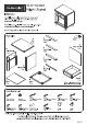
| . 2005170 0042 i Night Stand IMPORTANT Carefully remove all the parts from the carton and place therm individually on a soft cloth to prevent scratches or other damage. Carefully and strictly fol ow these assembly instructions to ensure a completed product as designed. Do not use power tools above 8 volts to assemble. 1 pe. -~ Part List J 6 Foot A D. 4 pes. Top Front Rail pes. 1 pe. 1pe. K E Back Anal Front Rail pe. Side Panel 1pe. J % F. Front Rail 1pe. < G Side Panel e Feral Back Rai 1pe.
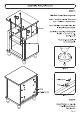
( Assembly Instructions 2/8 ] IMPORTANT » Use & soft cloth between these parts and the floor. * Do not use power tools above 8 volts to assemble. » Do not tighten all the screws until each part 's properly assembled, » Tha unit must be level to work properly. Use the included adjustable levelers to level. § @ cam Lock Resew STEP 1 insert Cam Lock Screws into per-drilled holes of Top (A), Side Panels (B), (C) and Front Ra'l (F}, then tighten.
( Assembly Instructions 3/8 ] STEP 3 Attach Front Rails (D}, (E} and unit to Side Panel (B} with Cam Locks. STEP 4 Attach Side Panel (C) to unit with Cam Locks. HE.
Assembly Instructions 5/8 ] STEP Slide Back Panel (K} into the groove. Attach Top (A) to unit with Cam Locks and 1 1/4" Round Head Screws. Note: A Phillips screwdriver 5 or less in length is recommended. Lee! unit by adjusting the adjustable levelers on bottom of unit. {See Figure 2) Note: Unit must be level to work properly, 114" Round Head Screw M) Figure 2 e, 142" Fiat Head Screw >f / Wedge —3 Figure 3 STEP 8 Attach Wadges to unit with 1/2" Flat Head Screws. {See Figure 3) HE.
( Assembly Instructions 6/8 ] STEP 9 Attach Drawer Sides (L3} and {L4) to Drawer Back {12) with 11/4" Flat Head Screws. STEP 10 114" Fat Herod Screw Insert Drawer Bottom (L5} into the groove. Attach Drawer Front (L1) to unit with 1 1/4" Flat Head Resews. Musing Se raw _* @ \ Handle Note: Drawer assembly is not complete until 3/4” Flat Head Screws are used in a later step. STEP 11 Attach Hand'e with Machine Screw. Drawer Side % Drawer Side Drawer Bottom 1pe 1pe 1pe. Tpe.
( Assembly Instructions 7/8 ] STEP 12 Leo sen slightly screws per-installed on back of drawer front. g%’ E— — STEP 13 Insert drawer into unt, then adjust drawer front panel left or right and up or down until drawer gaps look proportional. STEP 14 Pull drawer pane slowly and re-tighten screws from Step 12, Make sure drawer front panel does not move and lock drawer front panel into position with 3/4" Flat Head Screws. Note: These 3/4" Flat Head Screws must be installed to complete the drawer assembly.