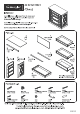
20 05525 0041 LT Ty Chest IMPORTANT Carefully remove all the parts from the carton and place therm individually on a soft cloth to prevent scratches or other damage. Carefully and strictly fol ow these assembly instructions to ensure a completed product as designed. De not use power tools above 8 volts to assemble. r ~ Part List A. H. Top Back Panel 1pe. 2 pes. I to. Drawer Front Rail Front Rail 8, Cc E. Tee 5 Side Anal Side Panel Front Ral : 1pe 1pe. 3 pes. Drawer 2 pes.
( Assembly Instructions 2/11 ) IMPORTANT » Use a soft cloth between these parts and the floor. + Do not use power tools above 8 volts to assemble. » Do not tighten all the screws unt] each part 's properly assembled, Tha unit must be level to work properly. Use the included adjustable levelers to level. STEP 1 Insert Cam Lock Screws into per-drilled Jo—cam Lack Screw holes in Top {A}, Side Panels (B), (C) and | Back Panels (H}, then tighten.
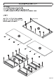
( Assembly Instructions 3/11 ) STEP 2 Assemble Back Panels (H) with Cam Locks. {See Figure 1) STEP 3 Attach Front Rails (D}, (E), (F) and back panel unit to Side Panel (B) with Cam Locks.
( Assembly Instructions 4/11 ) STEP 4 Attach Side Panel (C} to unit with Cam Locks, STEPS Attach Bottom (G) to unit with Wooden Dowels, Cam Locks and 1 1/4" Round Head Screws.
( Assembly Instructions 5/11 ) STEP 6 Attach Top (A) to unit with Wooden Dowels, Cam Locks and 1 3/4" Round Head Screws. Note: A Phillips screwdriver 5 or less in length is recommended. Lee! unit by adjusting the adjustable levelers on bottom of unit. 1344" Round Dash Se raw {See Figure 2) Note: Unit must be level to work properly.
( IMPORTANT Assembly Instructions 6/11 » Tar help reduce the risk of the unit tipping aver, the Tip over Restraint must be installed following these instructions exactly. STEP 7 Place unit at desired location. Mark wall with pencil just above and in-line with hole in Top (A). (See Figure 3) Move unit. Drill a 3/8" hole in wall 1 1/2* below mark. Insert Anchor into the wall hole and attach Restraint to Anchor with 1 1/2” Round Head Screw and Flat Washer.
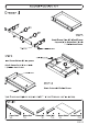
( Assembly Instructions 7/11 ) STEP 8 Attach Drawer Sides (13), (4) and Drawer Supports (16) to Drawer Back {12) with 11/4" Flat Head Screws. Roller at back STEP 9 Insert Drawer Bottom (15) into groove. Attach Drawer Front {11} to unit with 11/4" Flat Head Screws. STEP 10 Attach Knobs with Machine Screws. Note: Drawer assembly is not complete until 3/4” Flat Head Screws are used in a later step. ZZ > Drawer Front Drawer Back Drawer Fe Drawer Side Drawer Bottom Drawer Support 1 pe. 1pe. pes.
( Assembly Instructions 8/11 ) Drawer (J) STEP 11 Attach Drawer Sides (13), (4) and Drawer Supports (16) to Drawer Back {12) with 11/4" Flat Head Screws. Roller at back STEP 12 Insert Drawer Bottom (JB) into groove. Attach Drawer Front {11} to unit with 11/4" Flat Head Screws. Machine Screw STEP 13 Attach Knobs with Machine Screws. Note: Drawer assembly is not complete until 3/4” Flat Head Screws are used in a later step. ZZ > Drawer Front Drawer Back Drawer Fe Drawer Side Drawer Bottom Drawer Support 1 pe.
( Assembly Instructions 9/11 ) STEP 14 Attach Drawer Sides {K3), (K4) and Drawer Supports (16) to Drawer Back (K2) with 1 1/4" Flat Head Screws. Roller at back STEP 15 Insert Drawer Bottom (JB) into groove. Attach Drawer Front (K1} to unit with 11/4" Flat Head Screws. aching Sower S > STEP 16 Attach Handles with Machine Screws. Note: Drawer assembly is not complete until 3/4” Flat Head Screws are used in a later step. Drawer Back Drawer Front Drawer Side Drawer Side Drawer Bottom Drawer Support Z pes.
( Assembly Instructions 10/11 ) STEP 17 Loosen slightly the screws per-installed on back of drawer fronts. a STEP 18 UA Insert drawers into unit, then ae adjust drawer front panels left or right and up or down until a drawer gaps look proportional. STEP 19 Pull each drawer open slowly and re tighten screws from Step 17. Make sure drawer front panels do not move and lock drawer front panels into position with 3/4" Flat Head Screws.