DRAFT - Revised: 11-17-02 b Hardware Guide Sapphire Document Part Number: 309971-001 April 2003 [Abstract goes here, or delete this line.] Compa q CONFIDENTIAL—Fo r In tern al U se On ly 1 1/12/02 F i le: S a p ph ir e - In t r o .
DRAFT - Revised: 11-17-02 © 2003 HP HP notice Hardware Guide First Edition February 2003 Document Part Number: 309971-001 Compa q CONFIDENTIAL—Fo r In tern al U se On ly 1 1/12/02 F i le: S a p ph ir e - In t r o .
DRAFT - Revised: 10-28-02 Contents 1 Notebook Features Contents of the Packing Box . . . . . . . . . . . . . . . . . . . . . . 1–1 Notebook Features . . . . . . . . . . . . . . . . . . . . . . . . . . . . . . 1–2 Pointing Device Components . . . . . . . . . . . . . . . . . . 1–2 Top Components . . . . . . . . . . . . . . . . . . . . . . . . . . . . 1–3 Left Side Components . . . . . . . . . . . . . . . . . . . . . . . . 1–5 Right Side Components . . . . . . . . . . . . . . . . . . . . . . .
DRAFT - Revised: 10-28-02 Displaying System Information (Fn+Esc). . . . . . . . . 2–8 Using Hotkeys and Shortcut Keys with External Keyboards . . . . . . . . . . . . . . . . . . . . . . . . . . 2–9 Using Quick Launch Buttons . . . . . . . . . . . . . . . . . . . . . 2–10 Keypads . . . . . . . . . . . . . . . . . . . . . . . . . . . . . . . . . . . . . 2–11 Using the Internal Keypad. . . . . . . . . . . . . . . . . . . . 2–11 Using an External Keypad. . . . . . . . . . . . . . . . . . . .
DRAFT - Revised: 10-28-02 4 Hard Drive Caring for Drives . . . . . . . . . . . . . . . . . . . . . . . . . . . . . . . 4–1 Hard Drive Activity Light . . . . . . . . . . . . . . . . . . . . . . . . 4–2 Replacing the Primary Hard Drive. . . . . . . . . . . . . . . . . . 4–2 5 Audio and Video Using Audio Features. . . . . . . . . . . . . . . . . . . . . . . . . . . . Adjusting Volume . . . . . . . . . . . . . . . . . . . . . . . . . . . Using the Audio Line-In Jack . . . . . . . . . . . . . . . . . .
DRAFT - Revised: 10-28-02 8 Hardware Upgrades Using PC Cards . . . . . . . . . . . . . . . . . . . . . . . . . . . . . . . . 8–1 Inserting a PC Card . . . . . . . . . . . . . . . . . . . . . . . . . . 8–2 Removing a PC Card . . . . . . . . . . . . . . . . . . . . . . . . . 8–2 Using SD Cards . . . . . . . . . . . . . . . . . . . . . . . . . . . . . . . . 8–4 Inserting an SD Card . . . . . . . . . . . . . . . . . . . . . . . . . 8–4 Removing an SD Card. . . . . . . . . . . . . . . . . . . . . . . .
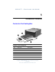
DRAFT - Revised:10-28-02 1 Notebook Features Contents of the Packing Box Contents of the Packing Box Item Component Description This is place-holder Hardware Guide Compa q CONFIDENTIAL—Fo r In tern al U se On ly 1 1/13/02 F il e : S P - C H 1 - N o t e bo o k F e a tu r e s .
DRAFT - Revised:10-28-02 Notebook Features Notebook Features Pointing Device Components Pointing Device Components Item Component Description 1 Pointing stick Moves the pointer and selects or activates items on the screen. 2 Left and right TouchPad buttons Function like the left and right buttons on an external mouse. 3 TouchPad Moves the pointer and selects or activates items on the screen. Can be set to perform other mouse functions, such as scrolling, selecting, and double-clicking.
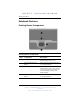
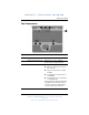
DRAFT - Revised:10-28-02 Notebook Features Top Components Top Components Item Component Description 1 Quick Launch buttons (6) Enable you to access common functions with a single keystroke. 2 Power/standby button When the notebook is*: ■ Off, press and release to turn on the notebook. ■ On, press and release to initiate Standby. ■ In Standby, press and release to exit Standby. ■ In Hibernation, press and release to exit Hibernation.
DRAFT - Revised:10-28-02 Notebook Features Top Components (Continued) Item Component Description 3 Function keys Execute frequently used system functions when pressed in combination with the Fn key. 4 Applications key Displays shortcut menu for items beneath the pointer. 5 Display release latch recess Secures the display when it is closed. 6 Microsoft logo key Displays the Windows Start menu. 7 Fn key Executes frequently used system functions when pressed in combination with another key.
DRAFT - Revised:10-28-02 Notebook Features Left Side Components Left Side Components Item Component Description 1 Infrared port Links another IrDA-compliant device for wireless communication. 2 PC Card eject button Ejects an optional PC Card from the PC Card slot. 3 PC Card slot Supports optional Type I or Type II 32-bit (CardBus) or 16-bit PC Cards. 4 Secure Digital (SD) slot Accepts SD memory cards to increase the memory capacity of the notebook.
DRAFT - Revised:10-28-02 Notebook Features Right Side Components Right Side Components Item Component Description 1 Security cable slot Attaches an optional security cable to the notebook. 2 Hard drive bay Holds the primary hard drive. 3 Exhaust vent Enables airflow to cool internal components. prevent overheating, do not ÄToobstruct vents. Using the notebook on a soft surface, such as a pillow, blanket, rug, or thick clothing may block airflow.
DRAFT - Revised:10-28-02 Notebook Features Front View Components Front View Components Item Component Description 1 Antenna (2) Send and receive internal wireless Local Area Network (LAN) signals. 2 Microphone Inputs single-channel sound. 3 Display release latch Opens the notebook. Hardware Guide Compa q CONFIDENTIAL—Fo r In tern al U se On ly 1 1/13/02 F il e : S P - C H 1 - N o t e bo o k F e a tu r e s .
DRAFT - Revised:10-28-02 Notebook Features Rear Panel Components Rear Panel Components Item Component Description 1 S-video out jack Connects an optional S-video device, such as a television, VCR, camcorder, overhead projector, or video capture card. 2 External monitor connector Connects an optional external monitor or overhead projector. 3 USB connector Connects USB devices. 4 USB with power connector Connects powered USB devices.
DRAFT - Revised:10-28-02 Notebook Features Rear Panel Components (Continued) Item Component Description 7 RJ-11 jack Connects a modem cable. 8 Rear panel connector cover Closes to cover the connectors. This cover can be removed by removing the screws that secure it to the notebook. Bottom Components Bottom Components Item Component Description 1 Travel battery connector Connects the optional travel battery bay.
DRAFT - Revised:10-28-02 Notebook Features Bottom Components (Continued) Item Component Description 3 Mini PCI compartment Contains the mini PCI wireless card. 4 Intake vents Enables airflow to cool internal components. prevent overheating, do not ÄToobstruct vents. Using the notebook on a soft surface, such as a pillow, blanket, rug, or thick clothing may block airflow. 5 Battery release latch Releases the primary battery pack from the battery bay.
DRAFT - Revised:10-28-02 Notebook Features Lights Item Component Description 1 Caps lock On: Caps lock is on. 2 Scroll lock On: Scroll lock is on. 3 Num lock On: Num lock is on or the embedded numeric keypad is enabled. 4 Hard drive activity On: The hard drive is being accessed. 5 Power/standby On: Power is turned on. Blinking: Notebook is in Standby.
DRAFT - Revised: 10-28-02 2 Pointing Devices and Keyboard Using a Pointing Device By default, the pointing stick and TouchPad components can be used interchangeably. Pointing device components Hardware Guide Compa q CONFIDENTIAL—Fo r In tern al U se On ly 1 1/13/02 File: SP-CH2-Keyboa rd.
DRAFT - Revised: 10-28-02 Pointing Devices and Keyboard Pointing Device Components Item Component Description 1 Pointing stick Moves the pointer and selects or activates items on the screen. 2 Left and right pointing stick button Functions like the left and right buttons on an external mouse. 3 TouchPad Moves the pointer and selects or activates items on the screen. Can be set to perform other mouse functions, such as scrolling, selecting, and double-clicking.
DRAFT - Revised: 10-28-02 Pointing Devices and Keyboard Replacing the pointing stick cap Using the TouchPad To move the pointer, slide your finger across the TouchPad surface in the direction you want to move the pointer. Use the left and right TouchPad buttons as you would the left and right buttons on an external mouse. Using an External Mouse An external USB mouse can be connected to the notebook using one of the USB connectors on the back panel.
DRAFT - Revised: 10-28-02 Pointing Devices and Keyboard Setting Pointing Device Preferences Mouse Properties in Windows enables you to change custom settings for pointing devices, including: ■ Enabling or disabling a pointing device. ■ TouchPad tapping, which enables you to tap the TouchPad once to select an object or twice to double-click an object. ■ Edge motion, which enables you to continue to scroll even though your finger has reached the edge of the TouchPad.
DRAFT - Revised: 10-28-02 Pointing Devices and Keyboard Using Hotkeys and Shortcut Keys Hotkeys and shortcut keys, which are preset combinations of the Fn key and another key, execute frequently used system functions. Fn and Function Keys Fn and function keys Item Component 1 Fn key 2 Function keys ■ A hotkey is a combination of the Fn key and one of the function keys. The icons on the function keys represent the hotkey functions available on your notebook.
DRAFT - Revised: 10-28-02 Pointing Devices and Keyboard Hotkey and Shortcut Key Quick Reference Function Key Combination to Activate Function Key Combination to Deactivate Function Display help Fn+F1 Fn+F1 Initiate Standby Fn+F3 Power/standby button Switch display and image Fn+F4 Fn+F4 Initiate Quick Controls Fn+F6 Enter Power-on password View battery charge information Fn+F8 Fn+F8 Adjust the screen brightness to a lower level Fn+F9 N/A Adjust the screen brightness to a higher level F
DRAFT - Revised: 10-28-02 Pointing Devices and Keyboard Initiate Standby (Fn+F3) The Fn+F3 hotkeys are set at the factory to initiate Standby. ■ When the notebook is on, press the Fn+F3 hotkeys to initiate Standby. When Standby is initiated, your work is saved in random access memory (RAM), the screen is cleared, and power is conserved. While the notebook is in Standby, the power/standby light blinks. ■ To exit Standby, briefly press the power/standby button.
DRAFT - Revised: 10-28-02 Pointing Devices and Keyboard Initiating Quick Controls (Fn+F6) Quick Control security features disable the keyboard and pointing device and clear the display. Before you can use the Quick Controls, you must set a power-on password and select Quick Control preferences. For more information, refer on this CD to the Software Guide, “Security” chapter. To initiate Quick Controls manually, press Fn+F6. To exit Quick Controls, enter your Windows password.
DRAFT - Revised: 10-28-02 Pointing Devices and Keyboard system BIOS date is the version number of the system ROM. ✎ The The BIOS date may display in a decimal format, for example, 10/19/2002 A.07. Using Hotkeys and Shortcut Keys with External Keyboards The following hotkeys and shortcut keys can be used as described with external keyboards: ■ Fn+esc ■ Fn+F8 ■ Fn+F6 To use hotkeys or shortcut keys on an external keyboard, press the scroll lock key twice, then the other key of the hotkey combination.
DRAFT - Revised: 10-28-02 Pointing Devices and Keyboard Using Quick Launch Buttons The 6 Quick Launch buttons enable you to access common functions with a single keystroke. Quick Launch buttons Item Component Description 1 Wireless On/Off button Turns the wireless Local Area Network (LAN) on and off. 2 Presentation Mode button Sets the notebook to presentation mode, which opens a user-defined application, folder, file, or Web site.
DRAFT - Revised: 10-28-02 Pointing Devices and Keyboard Item Component Description 4 Mute button Mutes and restores the system volume. 5 Volume - button Decreases the system volume level. To mute or restore volume, press both volume buttons at the same time. 6 Volume + button Increases the system volume level. To mute or restore volume, press both volume buttons at the same time.
DRAFT - Revised: 10-28-02 Pointing Devices and Keyboard Embedded numeric keypad components Item Component 1 num lock light 2 num lock key 3 Numeric keypad keys 4 Fn key Enabling and Disabling the Internal Keypad Press Fn+num lk to enable the embedded numeric keypad. The num lock light turns on. Press Fn+num lk again to return the keys to their standard keyboard functions.
DRAFT - Revised: 10-28-02 Pointing Devices and Keyboard Switching Key Functions on the Internal Keypad You can temporarily switch the functions of keys on the internal keypad between their standard keyboard functions and their keypad functions by using the Fn key or the Fn+shift key combination. ■ To change the functions of a keypad key to keypad functions while the keypad is off, press and hold the Fn key while pressing the keypad key.
DRAFT - Revised: 10-28-02 Pointing Devices and Keyboard Enabling or Disabling the Numeric Keypad at Startup To set the notebook to startup with a connected external keypad in num lock mode, set your preference in Computer Setup. For more information about using Computer Setup, refer on this CD to the Software Guide, “Setup and Diagnostic Utilities” section. To set the notebook to start up with the external keypad enabled: 1. Turn on or restart the notebook. 2.
DRAFT - Revised: 10/28/02 3 Battery Packs This notebook supports up to 2 lithium ion battery packs. The same type of battery pack can be used in the notebook battery bay and the optional travel battery. Battery pack Hardware Guide Compa q CONFIDENTIAL—Fo r In tern al U se On ly 1 1/13/02 File: SP-CH3-B attery.
DRAFT - Revised: 10/28/02 Battery Packs Inserting or Removing the Primary Battery Pack The notebook battery bay holds the primary battery pack. Ä CAUTION: To prevent the loss of information when removing a battery pack, when it is the only power source available to the system, initiate Hibernation or shut down the notebook before removing the battery pack. To insert the primary battery pack: 1. Align the battery pack with the notebook battery bay. 2. Snap the battery pack into place.
DRAFT - Revised: 10/28/02 Battery Packs To remove the primary battery pack: 1. Close the display and turn the notebook bottom-side up. 2. Slide the battery release latch 1. 3. After the battery pack tilts upward, remove it from the battery bay 2. Removing the primary battery pack Hardware Guide Compa q CONFIDENTIAL—Fo r In tern al U se On ly 1 1/13/02 File: SP-CH3-B attery.
DRAFT - Revised: 10/28/02 Battery Packs Using the Optional Travel Battery The optional travel battery holds the second battery pack and attaches to the bottom of the notebook with the travel battery connector. Inserting or Removing the Battery Pack To insert the battery pack into the travel battery: 1. Align the battery pack with the travel battery. 2. Snap the battery pack into place.
DRAFT - Revised: 10/28/02 Battery Packs To remove the battery pack from the travel battery: 1. Eject the battery pack from the travel battery by sliding the battery release latch 1. 2. When the battery pack tilts upward, remove it from the travel battery 2. Removing a battery pack from the travel battery Hardware Guide Compa q CONFIDENTIAL—Fo r In tern al U se On ly 1 1/13/02 File: SP-CH3-B attery.
DRAFT - Revised: 10/28/02 Battery Packs Attaching or Detaching the Travel Battery and the Notebook To attach the optional travel battery: 1. Open the travel battery connector on the bottom of the notebook by sliding the cover. Opening the travel battery connector 3–6 Hardware Guide Compa q CONFIDENTIAL—Fo r In tern al U se On ly 1 1/13/02 File: SP-CH3-B attery.
DRAFT - Revised: 10/28/02 Battery Packs 2. Align the tabs on the travel battery with the recesses on the bottom of the notebook. 3. Press the travel battery onto the notebook until it snaps into place. Attaching the travel battery Hardware Guide Compa q CONFIDENTIAL—Fo r In tern al U se On ly 1 1/13/02 File: SP-CH3-B attery.
DRAFT - Revised: 10/28/02 Battery Packs 4. Lock the travel battery onto the notebook by sliding the locking switch. Locking the travel battery onto the notebook 3–8 Hardware Guide Compa q CONFIDENTIAL—Fo r In tern al U se On ly 1 1/13/02 File: SP-CH3-B attery.
DRAFT - Revised: 10/28/02 Battery Packs To detach the travel battery from the notebook: 1. Unlock the travel battery from the notebook by sliding the locking switch 1. 2. Press the release latch 2. 3. Lift the travel battery up and away from the notebook 3. Detaching the travel battery from the notebook Charging a Battery Pack Multiple battery packs in the system charge and discharge in a preset sequence determined by location: ■ Charge sequence: 1. Notebook battery bay 2.
DRAFT - Revised: 10/28/02 Battery Packs The primary battery pack charges when it is inserted into the notebook and the notebook is connected to external power. External power can be supplied through an AC Adapter, the optional Advanced Port Replicator, or an optional Automobile Power Adapter/Charger. The battery pack in the travel battery charges when it is attached to the notebook and the notebook is connected to external power.
DRAFT - Revised: 10/28/02 Battery Packs To charge the primary battery pack: 1. Insert the battery pack into the notebook. 2. Connect the notebook to AC power. (The battery light turns on.) 3. Leave the notebook connected to AC power until the battery light turns off, signaling that the battery pack is fully charged. To charge the battery pack in the travel battery: 1. Insert the battery pack into the travel battery. 2. Attach the travel battery to the notebook. 3. Connect the notebook to AC power.
DRAFT - Revised: 10/28/02 Battery Packs Displaying Charge Information on the Screen To display battery charge information on the screen, use the Power meter feature of the operating system: ■ Select Start > Control Panel > Performance and Maintenance icon > Power Options icon > Power Meter tab. or ■ Select the Power meter icon in the system tray. To display the Power meter icon in the system tray: 1. Select Start > Control Panel > Performance and Maintenance icon > Power Options icon > Advanced tab. 2.
DRAFT - Revised: 10/28/02 Battery Packs Displaying Charge Information on a Battery Pack The battery Quick Check feature enables you to check the battery pack charge information. You do not have to remove a battery pack from the notebook battery bay or the travel battery to check the charge information; however, you must detach the travel battery from the notebook to check the charge of the travel bay battery pack.
DRAFT - Revised: 10/28/02 Battery Packs Battery Pack Quick Check Indications Indication Percent of a Full Charge Remaining 4 lights on 76 to 100% 3 lights on 51 to75% 2 lights on 26 to 50% 1 light on 11 to 25% 1 light blinking 1 to 10% Managing Low-Battery Conditions Some low-battery condition alerts and system responses can be changed in the Power Options Properties window of the operating system. The information in this chapter describes the alerts and system responses set at the factory.
DRAFT - Revised: 10/28/02 Battery Packs ■ If Hibernation is enabled and the notebook is on or in Standby, the notebook initiates Hibernation. ■ If Hibernation is disabled and the notebook is on or in Standby, the notebook remains in Standby until there is no power, then shuts down and loses your unsaved work. For more information about Hibernation and Standby, refer on this CD to the Software Guide, “Power” chapter.
DRAFT - Revised: 10/28/02 Battery Packs ■ Plug an optional Aircraft Power Adapter into the notebook and into the in-seat power supply available on some commercial aircraft. (The optional Aircraft Power Adapter can run the notebook but cannot charge a battery pack.) ■ Dock the notebook in an optional Port Replicator. When No Power Source Is Available Select one of the following options: ■ Initiate Hibernation. ■ Save your work and shut down the notebook.
DRAFT - Revised: 10/28/02 Battery Packs How to Calibrate Calibration requires 3 steps: 1. Fully charge the battery pack. 2. Fully discharge the battery pack. 3. Fully recharge the battery pack. Charging the Battery Pack You can charge the battery pack while the notebook is on or off, but the battery pack charges faster while the notebook is off. Fully charge the battery pack according to the “Charging a Battery Pack” section earlier in this chapter.
DRAFT - Revised: 10/28/02 Battery Packs To fully discharge a battery pack: 1. When the battery light turns off indicating that the battery pack is fully charged, select Start > Control Panel > Performance and Maintenance icon > power Options icon > Power Schemes tab. 2. Make a note of the 2 settings in the Plugged In column and the 2 settings in the Running On Batteries column so that you can reset them after the calibration. 3. Change the settings in both columns to Never. 4. Select the OK button. 5.
DRAFT - Revised: 10/28/02 Battery Packs 4. Referring to the settings you made note of earlier, change the settings for the 2 options in the Plugged In column and the 2 options in the Running On Batteries column. 5. Select the OK button. Conserving Battery Power Using the battery conservation procedures and settings described below extends the time that a battery pack can run the notebook from a single charge.
DRAFT - Revised: 10/28/02 Battery Packs Selecting Power Conservation Settings To set the notebook to conserve power: 3–20 ■ Select a short wait for the screen saver and select a screen saver with minimal graphics and motion. To access screen saver settings by selecting Start > Control Panel > Appearance and Themes > Display icon > Screen Saver tab.
DRAFT - Revised: 10/28/02 Battery Packs Storing a Battery Pack If a notebook will be unused and unplugged for more than 2 weeks, remove and store the battery pack. Ä CAUTION: To prevent damage to a battery pack, do not expose it to high temperatures for an extended time. High temperatures accelerate the self-discharge rate of a stored battery pack. To prolong the charge of a stored battery pack, store it in a cool, dry place within the following temperature ranges.
DRAFT - Revised: 10/28/02 Battery Packs Disposing of a Used Battery Pack Å WARNING: There is a risk of fire and chemical burn if a battery pack is handled improperly. Do not disassemble, crush, or puncture a battery pack or short the contacts on a battery pack. Do not expose a battery pack to temperatures higher than 60°C (140°F) or dispose of a battery pack in water or fire. When a battery pack has reached the end of its useful life, do not dispose of it in general household waste.
DRAFT - Revised: 10-28-02 4 Hard Drive Caring for Drives Hard drives are fragile notebook components that must be handled with care. Please read carefully the general caution notices provided below. Caution notices specific to individual procedures are provided throughout this chapter with the procedures to which they apply. Ä■ CAUTION: To prevent loss of work or damage to the notebook or a drive: Handle the drive carefully. ■ Do not drop the drive. ■ Excessive force can damage drive connectors.
DRAFT - Revised: 10-28-02 Hard Drive security devices that check carry-on luggage placed on a ✎ Airport conveyor belt use X-rays instead of magnetism and do not damage hard drives. Hard Drive Activity Light The hard drive activity light turns on when the hard drive is being accessed. Hard drive activity light Replacing the Primary Hard Drive The hard drive in the hard drive bay is the primary hard drive.
DRAFT - Revised: 10-28-02 Hard Drive To replace the primary hard drive: 1. Save your work. 2. Shut down the notebook and close the display. 3. Turn the notebook bottom-side up. 4. Remove the hard drive retaining screw. Removing the hard drive retaining screw Hardware Guide Compa q CONFIDENTIAL—Fo r In tern al U se On ly 1 1/13/02 File: SP-CH4-Har d Drive s.
DRAFT - Revised: 10-28-02 Hard Drive 5. Remove the hard drive bezel. Removing the hard drive bezel 4–4 Hardware Guide Compa q CONFIDENTIAL—Fo r In tern al U se On ly 1 1/13/02 File: SP-CH4-Har d Drive s.
DRAFT - Revised: 10-28-02 Hard Drive 6. Pull the drive out of the bay. Removing the hard drive from the hard drive bay Hardware Guide Compa q CONFIDENTIAL—Fo r In tern al U se On ly 1 1/13/02 File: SP-CH4-Har d Drive s.
DRAFT - Revised: 10-28-02 Hard Drive 7. Insert a hard drive by sliding the hard drive into the bay until the drive is seated. Inserting the hard drive into the hard drive bay 4–6 Hardware Guide Compa q CONFIDENTIAL—Fo r In tern al U se On ly 1 1/13/02 File: SP-CH4-Har d Drive s.
DRAFT - Revised: 10-28-02 Hard Drive 8. Replace the hard drive bezel. Replacing the hard drive bezel Hardware Guide Compa q CONFIDENTIAL—Fo r In tern al U se On ly 1 1/13/02 File: SP-CH4-Har d Drive s.
DRAFT - Revised: 10-28-02 Hard Drive 9. Reinsert the hard drive retaining screw. (If you removed but did not replace a hard drive, put the retaining screw in a safe place.) Replacing the hard drive retaining screw 4–8 Hardware Guide Compa q CONFIDENTIAL—Fo r In tern al U se On ly 1 1/13/02 File: SP-CH4-Har d Drive s.
DRAFT - Revised: 10-28-02 5 Audio and Video Using Audio Features The notebook provides the following audio components: Audio components Audio Components Item Component Description 1 Mute button Mutes system volume. 2 Volume buttons (2) Adjust the system volume. 3 Audio line-in jack Connects an optional single-sound channel microphone. Hardware Guide Compa q CONFIDENTIAL—Fo r In tern al U se On ly 1 1/13/02 File: SP-CH5-A udio and Video.
DRAFT - Revised: 10-28-02 Audio and Video Audio Components (Continued) Item Component Description 4 Audio line-out jack Connects optional, powered stereo speakers, headphones, headset, or television audio. 5 Speaker Produces stereo sound. 6 Microphone Inputs single-channel sound. Adjusting Volume To adjust the volume, use any of the following controls: ■ ■ Notebook volume buttons ❏ To mute or restore volume, press the Quick Launch mute button.
DRAFT - Revised: 10-28-02 Audio and Video Using the Audio Line-In Jack When an external microphone is connected to the notebook, the notebook microphone is disabled. When connecting a microphone to the audio line-in jack, use a single-sound channel (monaural) microphone with a 3.5-mm plug. A monaural electret condenser microphone is recommended. Other types of microphones are not fully functional with the notebook: ■ If you connect a stereo microphone, left channel sound will record on both channels.
DRAFT - Revised: 10-28-02 Audio and Video card. The notebook supports one S-video device connected to the S-video-out jack while simultaneously supporting an image on the notebook display and on any other supported external display. To transmit video signals through the S-video-out jack, you need an S-video cable available from most electronic retailers.
DRAFT - Revised: 10-28-02 Audio and Video the S-video-out jack on the notebook is not accessible while the ✎ Ifnotebook is docked, you can connect the device to the S-video-out jack on the optional Port Replicator. Changing the Video Mode The default color television standard mode of the notebook is NTSC. Color television standard modes vary even within regions.
DRAFT - Revised: 10-28-02 6 Communication Devices Connecting a Modem Cable A modem cable, which has a 6-pin RJ-11 connector at each end, must be connected to an analog telephone line. Jacks for digital PBX systems may resemble analog telephone jacks, but are not compatible with the modem. Å WARNING: Connecting the notebook to a digital line can permanently damage the modem. Immediately disconnect your modem cable if accidentally connected to a digital line.
DRAFT - Revised: 10-28-02 Communication Devices If the modem cable contains noise suppression circuitry, which prevents interference from TV and radio reception, orient the circuitry end of the cable toward the notebook. RJ-11 modem cable with noise suppression circuitry 6–2 Hardware Guide Compa q CONFIDENTIAL—Fo r In tern al U se On ly 1 1/13/02 File: SP-CH6-Communic ation De vic es.
DRAFT - Revised: 10-28-02 Communication Devices Using the RJ-11 Cable To connect an RJ-11 modem cable: 1. Plug the modem cable into the RJ-11 jack on the notebook 1. Å WARNING: To reduce the risk of electrical shock, fire, or damage to the equipment, do not plug a telephone cable into the RJ-45 network jack. 2. Plug the modem cable into the RJ-11 telephone jack 2.
DRAFT - Revised: 10-28-02 Communication Devices Using a Country-Specific Adapter Cable Telephone jacks vary by country. To use the modem and the RJ-11 cable outside the country in which you purchased the notebook, you must obtain a country-specific modem adapter. Refer on this CD to the Modem and Networking guide for more details about using your notebook internationally. To connect the modem to an analog telephone line that does not have an RJ-11 telephone jack: 1.
DRAFT - Revised: 10-28-02 Communication Devices Connecting a Network Cable A network cable has an 8-pin RJ-45 connector at each end. If the network cable contains noise suppression circuitry, which prevents interference from TV and radio reception, orient the circuitry end of the cable toward the notebook. RJ-45 network cable with noise suppression circuitry Hardware Guide Compa q CONFIDENTIAL—Fo r In tern al U se On ly 1 1/13/02 File: SP-CH6-Communic ation De vic es.
DRAFT - Revised: 10-28-02 Communication Devices To connect the network cable: 1. Plug the network cable into the RJ-45 jack on the notebook 1. 2. Plug the other end of the cable into a network jack 2. Connecting a network cable 3. Start or restart the notebook. 4. Connect to the network. Linking to an Infrared Device The notebook is IrDA-compliant—4 megabits per second (Mbps) standard—and can communicate with another infrared-equipped device that is also IrDA-compliant.
DRAFT - Revised: 10-28-02 Communication Devices Infrared signals are sent through an invisible beam of infrared light and require an unobstructed line of sight path. Linking to an infrared device The infrared port supports both low speed connections of up to 115 kilobits per second (Kbps) and high speed connections of up to 4 Mbps. Infrared performance may vary depending on the performance of infrared peripherals, distance between infrared devices, and applications used.
DRAFT - Revised: 10-28-02 Communication Devices ■ Shield the ports from direct sunlight, flashing incandescent light, and energy-saving fluorescent light. ■ Be sure that no signals from remote control or other wireless devices, such as headphones or audio devices, aim at a port. ■ During the transmission, do not move either device and do not allow objects or movement to disrupt the beam. Using Standby with Infrared Standby is not compatible with infrared transmission.
DRAFT - Revised: 10-28-02 7 External Devices The jacks and connectors described in this guide support the standard external devices that specify them. ■ For information about which jack or connector to use, refer to the documentation included with the device. ■ For information about installing or loading any software, such as drivers, required by the device, refer to the documentation included with the device. To connect a standard external device to the notebook: 1. Turn off the notebook. 2.
DRAFT - Revised: 10-28-02 External Devices a properly connected external monitor or projector does not ✎ Ifdisplay an image, try pressing the Fn+F4 hotkeys to switch the image to the monitor. Using a USB Device Universal serial bus (USB) is a hardware interface that can be used to connect external devices, such as a USB keyboard, mouse, drive, printer, scanner, or hub, to the notebook. The notebook has a USB connector 1 and a USB connector with power 2. The USB connectors support USB 2.0 and USB 1.
DRAFT - Revised: 10-28-02 External Devices Using a USB Device A USB device functions in the same way as a comparable non-USB device, with one exception. By default, USB devices do not function unless an operating system that supports USB is loaded. Some USB devices may require additional support software, which is usually included with the device. For more information and software installation instructions, refer to the documentation included with the device.
DRAFT - Revised: 10-28-02 External Devices Using an Optional External MultiBay An external MultiBay connects to the notebook using the USB with power connector. For more information about the external MultiBay, refer to the documentation that is included with the device. Connecting an external MultiBay 7–4 Hardware Guide Compa q CONFIDENTIAL—Fo r In tern al U se On ly 11/7/02 File : SP-CH7 -Ex t ernal De vices.
DRAFT - Revised: 10-28-02 External Devices Connecting an Optional Cable Lock To install a security cable: 1. Loop the security cable around a secured object. 2. Pull the security cable lock through the cable loop and insert the cable 1 into the security cable slot on the notebook. 3. If the cable has a key 2, use it to lock and unlock the cable. Connecting a security cable Hardware Guide Compa q CONFIDENTIAL—Fo r In tern al U se On ly 11/7/02 File : SP-CH7 -Ex t ernal De vices.
DRAFT - Revised: 10-28-02 8 Hardware Upgrades To order hardware or learn more about upgrades and accessories, visit the HP Web site at http://www.hp.com or contact an authorized dealer, reseller, or service provider. For information about obtaining and installing software updates and upgrades, refer on this CD to the Software Guide, “Software Updates and Restorations” chapter.
DRAFT - Revised: 10-28-02 Hardware Upgrades Inserting a PC Card Ä■ CAUTION: To prevent damage to the connectors: Use minimal pressure when inserting a PC Card into a PC Card slot. ■ Do not move or transport the notebook while a PC Card is inserted. To insert a PC Card: 1. Hold the PC Card label-side up with the connector facing the notebook. 2. Gently push the card into the slot until the card is seated.
DRAFT - Revised: 10-28-02 Hardware Upgrades To remove a PC Card: 1. Stop the PC Card: ❏ In Windows 2000 Professional, select the Unplug or Eject icon in the task bar, then stop the card you plan to remove. (When the card can be safely removed, a message is displayed.) ❏ In Windows XP Professional, select the Sfely Remove Hardware icon in the taskbar, then select the PC Card. (To display the Safely Remove Hardware icon, select Show Hidden Icons in the taskbar.) 2. Press the PC Card eject button 1. 3.
DRAFT - Revised: 10-28-02 Hardware Upgrades Using SD Cards Secure Digital (SD) cards are postage stamp-sized accessories that increase the memory capacity of your notebook. Inserting an SD Card Ä■ CAUTION: To prevent damage to the connectors: Use minimal pressure when inserting an SD card into an SD card slot. ■ Do not move or transport the notebook while an SD card is inserted. To insert an SD card: 1. Insert the SD card into the SD slot. 2.
DRAFT - Revised: 10-28-02 Hardware Upgrades Removing an SD Card Ä CAUTION: To prevent loss of work or system lockup, stop the SD card before removing it. To remove an SD card: 1. Close all files and applications using the SD card. 2. Stop the SD card. ❏ In Windows 2000 Professional, select the Unplug or Eject icon in the task bar, then stop the card you plan to remove. (When the card can be safely removed, a message is displayed.
DRAFT - Revised: 10-28-02 Hardware Upgrades Adding and Upgrading Memory Boards Å WARNING: The memory compartments are the only user-accessible internal compartments on the notebook. All other areas that require a tool to access should be opened only by an authorized service provider. Å WARNING: Failure to unplug the power cord and remove all battery packs before installing a memory expansion board can damage the equipment and expose you to the risk of electrical shock.
DRAFT - Revised: 10-28-02 Hardware Upgrades 4. Turn the notebook bottom-side up. 5. Remove any battery packs from the notebook. 6. Remove the screw from the memory expansion slot cover 1. 7. Remove the memory expansion slot cover 2. Removing the expansion slot cover Hardware Guide Compa q CONFIDENTIAL—Fo r In tern al U se On ly 1 1/13/02 F il e : S P -C H 8 - H a r dw a r e U p gr a de s .
DRAFT - Revised: 10-28-02 Hardware Upgrades 8. Insert the memory expansion board: a. Align the keyed (notched) edge of the board with the keyed area in the expansion slot 1. b. Press the board into the slot from a 45-degree angle until it is seated, then push the board downward until the retention clips snap into place 2. Inserting a memory expansion board 8–8 Hardware Guide Compa q CONFIDENTIAL—Fo r In tern al U se On ly 1 1/13/02 F il e : S P -C H 8 - H a r dw a r e U p gr a de s .
DRAFT - Revised: 10-28-02 Hardware Upgrades 9. Replace the expansion slot cover over the expansion board compartment 1. 10. Replace the expansion slot cover screw 2. 11. Replace the battery packs. 12. Reconnect AC power and external devices. 13. Restart the notebook. Upgrading the Memory Board in the Primary Memory Slot To upgrad the memory board in the primary memory slot: 1. Shut down the notebook.
DRAFT - Revised: 10-28-02 Hardware Upgrades 4. Remove any battery packs from the notebook. 5. Remove the 4 keyboard screws from the bottom of the notebook. A keyboard icon is located next to the keyboard screws. Removing the keyboard screws 8–10 Hardware Guide Compa q CONFIDENTIAL—Fo r In tern al U se On ly 1 1/13/02 F il e : S P -C H 8 - H a r dw a r e U p gr a de s .
DRAFT - Revised: 10-28-02 Hardware Upgrades 6. Using a fingernail or small flat tool, remove the Quick Launch button bezel located above the keyboard. Removing the Easy Access button bezel 7. Remove the keyboard. Removing the keyboard Hardware Guide Compa q CONFIDENTIAL—Fo r In tern al U se On ly 1 1/13/02 F il e : S P -C H 8 - H a r dw a r e U p gr a de s .
DRAFT - Revised: 10-28-02 Hardware Upgrades 8. Remove the existing memory board: a. Pull away the retention clips on each side of the board 1. (The board tilts upward.) b. Lift the edge of the memory expansion board, then gently pull it out of the slot 2. Removing the existing memory board protect a memory board after it has been removed, place it in ✎ Toan static-safe container.
DRAFT - Revised: 10-28-02 Hardware Upgrades 9. Insert the upgraded memory board: a. Align the keyed (notched) edge of the board with the keyed area in the expansion slot 1. b. Press the board into the slot from a 45-degree angle until it is seated, then push the board downward until the retention clips snap into place 2. Inserting the upgraded memory board 10. Replace the keyboard. 11. Replace the Quick Launch button bezel. 12. Replace the keyboard screws located on the bottom of the notebook. 13.
DRAFT - Revised: 10-28-02 Hardware Upgrades Increasing RAM You can increase the random access memory (RAM) of the notebook with optional PC Cards or memory expansion boards. When RAM increases, the operating system increases the hard drive space reserved for the hibernation file. If you experience problems with Hibernation after increasing RAM, verify that your hard drive has enough free space for the larger hibernation file.
DRAFT - Revised: 11-17-02 A Specifications Notebook Dimensions Dimension Metric U.S. Height 2.79 cm 1.1 in. Width 27.94 cm 11 in. Depth 23.37 cm 9.2 in. Operating Environment Factor Metric U.S.
DRAFT - Revised: 11-17-02 Specifications Rated Input Power Input Power Rating Operating voltage 100–120/220–240 VAC RMS Operating current 1.6/0.8 A RMS Operating frequency range 50–60 Hz AC When powered by a DC source 18.5V MAX product is designed for IT power systems in Norway ✎ This with phase-tophase voltage not exceeding 240 Vrms.
DRAFT - Revised: 11-17-02 B Regulatory Notices This notebook has been tested and found to comply with limits for a Class B digital device. Regulatory Notices For additional governmental agency information, refer on this CD to Regulatory and Safety Notices. Wireless Notices In some situations or environments, the use of wireless devices may be restricted by the proprietor of the building or responsible representatives of the organization.
DRAFT - Revised: 11-17-02 Regulatory Notices Å WARNING: Exposure to Radio Frequency Radiation The radiated output power of this device is far below the FCC radio frequency exposure limits. Nevertheless, the device should be used in such a manner that the potential for human contact during normal operation is minimized. In order to avoid the possibility of exceeding the FCC radio frequency exposure limits, human proximity to the antenna should not be less than 20 cm (8 inches) during normal operation.
DRAFT - Revised: mm/dd/yy Index Index A AC Adapter 1–8 Aircraft Power Adapter (optional) 1–8 airflow 1–6, 1–10 altitude specifications 9–1, 9–2 analog vs.
DRAFT - Revised: mm/dd/yy Index mute 2–11, 5–1, 5–2 PC Card, eject 1–5 pointing stick 1–2, 2–2 power/standby 1–3 Presentation Mode 2–10 TouchPad 1–2, 2–2 volume - 2–11, 5–1 volume + 2–11, 5–1 wireless 2–10 C calibrating battery packs 3–16 Caps lock light 1–11 connector docking 1–9 connectors DC power 1–8 external monitor 1–8 travel battery 1–10 USB 1–8 contents of packing box 1–1 country-specific modem adapter 6–4 D DC power connector 1–8 digital vs.
DRAFT - Revised: mm/dd/yy Index removing 4–3 replacing 4–2, 4–6 retaining screw 4–3, 4–8 space on, required for Hibernation file 8–14 viewing amount of free space on 8–14 headphones, headset (optional) 1–5 help and support 2–6 Hibernation file, space requirements of 8–14 hotkey quick reference 2–6 hotkeys defined 2–5 hotkeys commands adjusting screen brightness 2–8 initiate Standby 2–7 initiating quick controls 2–8 switching display and image 2–7 system information 2–8 viewing battery charge information 2–
DRAFT - Revised: mm/dd/yy Index expansion compartment 1–10 memory expansion board 8–6 slots, location 1–4 upgrading 8–6, 8–9 microphone 5–2 internal 1–7, 5–2 microphone jack 1–5, 5–1, 5–3 Microsoft logo key 1–4 mini PCI compartment 1–10 wireless card 1–9 modem cable 6–1, 6–3 connecting 6–1, 6–3 country-specific, adapter 6–4 monitor external, connector 1–8 monitor, connecting external 7–1 Mouse Properties utility 2–4 mouse, external 2–3 MultiBay (optional) 7–4 mute button 2–11, 5–1, 5–2 N network cable 6–5
DRAFT - Revised: mm/dd/yy Index jack 1–8 projector, connecting 7–1 Q T Quick Check 3–13 temperature operating 9–1, 9–2 TouchPad buttons 1–2, 2–2 location 1–2 using 2–3 travel battery attaching 3–6 battery packs 3–4 detaching 3–9 traveling with the notebook operating environment specifications 9–1, 9–2 R RAM (random access memory) 8–14 release latch 1–4 RJ-11 jack connecting 6–1, 6–3 S scroll lock key 2–9 Scroll lock light 1–11 SD cards inserting 8–4 removing 8–5 security cable connecting 7–5 slot 1–
DRAFT - Revised: mm/dd/yy Index volume + button 2–11 volume - button 5–1 volume + button 5–1 volume, adjusting 5–2 W wireless antenna 1–7 Index–6 button 2–10 infrared 6–6 infrared port 1–5 LAN 6–8 mini PCI compartment 1–10 on/off light 1–11 Manual Title Variable Compa q CONFIDENTIAL—Fo r In tern al U se On ly 1 1/13/02 File: 3 0997 1-00 1IX.