The engine exhaust from this product contains chemicals known to the State of California to cause cancer, birth defects or other reproductive harm. Keep this owner’s manual handy, so you can refer to it at any time. This owner’s manual is considered a permanent part of the water pump and should remain with the water pump if resold. The information and specifications included in this publication were in effect at the time of approval for printing. Honda Motor Co., Ltd.
INTRODUCTION Congratulations on your selection of a Honda water pump. We are certain you will be pleased with your purchase of one of the finest water pumps on the market. We want to help you get the best results from your new water pump and to operate it safely. This manual contains the information on how to do that; please read it carefully. As ou read this manual, you will find information preceded by a &iq symbol.
INTRODUCTION A FEW WORDS ABOUT SAFETY Your safety and the safety of others are very important. water pump safely is an important responsibility. And using this To help you make informed decisions about safety, we have provided operating procedures and other information on labels and in this manual. This information alerts you to potential hazards that could hurt you or others.
CONTENTS PUMP SAFETY ........................................................................................... ................................................. IMPORTANT SAFETY INFORMATION SAFETY LABEL LOCATIONS .... . ............................................................ 5 5 7 CONTROLS & FEATURES .. ... ... .. ... ... .. ... ... .. .... .. ... ... .. ... ... .. ... ...~.................. 8 COMPONENT & CONTROL LOCATIONS . ... .. .... .. .. .... .. .. ...a................... 8 CONTROLS ... ... ..
CONTENTS SERVICING YOUR HONDA PUMP (continued) ................................................... ENGINE OIL RECOMMENDATIONS AIR FILTER INSPECTION ..................................................................... AIR FILTER CLEANING ........................................................................ SEDIMENT CUP CLEANING ................................................................ SPARK PLUG SERVICE ........................................................................ ......................
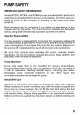
PUMP SAFETY IMPORTANT SAFETY INFORMATION Honda WT20X, WT30X, and WT40X pumps are designed to pump only water that is not intended for human consumption, and other uses can result in injury to the operator or damage to the pump and other property. Most accidents can be prevented if you follow all instructions in this manual and on the pump. The most common hazards are discussed below, along with the best way to protect yourself and others.
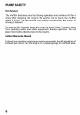
PUMP SAFETY Hot Exhaust The muffler becomes very hot during operation and remains hot for a while after stopping the engine. Be careful not to touch the muffler while it is hot. Let the engine cool before transporting the pump or storing it indoors. To prevent fire hazards, keep the pump at least 3 feet (1 meter) away from building walls and other equipment during operation. Do not place flammable objects close to the engine.
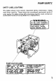
PUMP SAFETY SAFETY LABEL LOCATIONS The labels shown here contain important safety information. Please read them carefully. These labels are considered permanent parts of your pump. If a label comes off or becomes hard to read, contact an authorized Honda servicing dealer for a replacement. \~ETERSO~AL PUMP CAUTION INJURY.
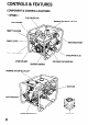
CONTROLS & FEATURES COMPONENT & CONTROL LOCATIONS FUEL FILLER CAP PRIMING/WATER FILLER CAP AIR CLEANER THROTTLE LEVER CHOKE LEVER ‘DISCHAR,GE PORT FUEL VALVE L CASE DRAIN PIJJG STARTER GRIP OIL FlLiER CAP/DIPSTICK / IGNITION SWITCH PRIMING WATER FILLER CAP , SUCTION MUFFLER PORT COVER DRAIN PLUG t STRAINER
CONTROLS & FEATURES CONTROLS Fuel Valve Lever The fuel valve opens and closes the connection between the fuel tank and the carburetor. FUEL VALVE LEVER The fuel valve lever must be in the ON position for the engine to run. When the engine is not in use, leave the fuel valve lever in the OFF position to prevent carburetor flooding and to reduce the possibility of fuel leakage. OFF -I Ignition Switch IGNITION SWITCH The ignition switch ignition system.
CONTROLS & FEATURES Choke Lever The choke lever opens and closes the choke valve in the carburetor. CHOKE LEVER ! I The CLOSED position enriches the fuel mixture for starting a cold engine. The OPEN position provides the correct fuel mixture for operation after starting, and for restarting a warm engine. Throttle Lever The throttle speed. lever controls engine Moving the throttle lever in the directions shown makes the engine run faster or slower.
CONTROLS & FEATURES Recoil Starter Grip Pulling the starter grip operates the recoil starter to crank the engine. STARTER GRIP FEATURES Oil Alert@ System The Oil Alert@ system is designed to prevent engine damage caused by an insufficient amount of oil in the crankcase. Before the oil level in the crankcase can fall below a safe limit, the Oil Alert@ system will automatically stop the engine (the ignition switch will remain in the ON position).
BEFORE OPERATION ARE YOU READY TO GET STARTED? Your safety is your responsibility. A little time spent in preparation significantly reduce your risk of injury. will Knowledge Read and understand how to operate them. this manual. Know what the controls Familiarize yourself with the pump and its operation pumping. Know what to do in case of emergencies. before you begin Be sure of what you are pumping. This pump is designed only water that is not intended for human consumption.
BEFORE OPERATION IS YOUR PUMP READY TO GO? For your safety, and to maximize the service life of your equipment, it is very important to take a few moments before you operate the pump to check its condition. Be sure to take care of any problem you find, or have your servicing dealer correct it, before you operate the pump. Improperly maintaining this pump, or failing to correct a problem before operation, could cause a malfunction in which you could be seriously injured.
BEFORE OPERATION Check the Suction and Discharge Hoses l l l l Check the general condition of the hoses. Be sure the hoses are in serviceable condition before connecting them to the pump. Remember that the suction hose must be reinforced construction to prevent hose collapse. Check that the sealing washer good condition (see page 17 ). in the suction Check that the hose connectors (see pages 17& 18). and clamps Check that the strainer is in good condition suction hose (see page 17 ).
OPERATION SAFE OPERATING PRECAUTIONS To safely realize the full potential of this pump, you need a complete understanding of its operation and a certain amount of practice with its controls. Before operating the pump for the first time, please review the IMPORTANT SAFETY INFORMATION on page 5 and the chapter titled BEFORE OPERA TION. For your safety, avoid starting or operating the engine in an enclosed area, such as a garage.
OPERATION PUMP PLACEMENT For best pump performance, place the pump near the water level, and use hoses that are no longer than necessary. That will enable the pump to produce the greatest output with the least self-priming time. As head (pumping height) increases, pump output decreases. Maximum head specifications and pump performance curves are shown in the tables on pages 57,59 and 61 . The length, type, and size of the suction and discharge hoses can also significantly affect pump output.
OPERATION SUCTION HOSE INSTALLATION Use the commercially available hose and hose connector with the hose clamp provided with the pump. The suction hose must be reinforced with a noncollapsible wall or braided wire construction. The suction hose should be no longer than necessary. Pump performance is best when the pump is near the water level, and the hoses are short. Use a hose clamp to securely fasten the hose connector hose in order to prevent air leakage and loss of suction.
OPERATION DISCHARGE HOSE INSTALLATION HOSE CONNECTOR Use a commercially available hose with the hose connector and clamp provided with the pump. It is best to use a short, largediameter hose, because that will reduce fluid friction and improve pump performance. A long or small-diameter hose will increase fluid friction and reduce pump output. Tighten the hose clamp securely to prevent the discharge hose from disconnecting under high pressure.
1 OPERATION / STARTING THE ENGINE 1. Move the fuel valve lever to the ON position. FUEL VALVE LEVER i i I , i i \ 2. To start a cold engine, move the choke lever to the CLOSED position. To restart a warm engine, leave the choke lever in the OPEN position. CHOKE LEVER 3. Move the throttle lever away from the SLOW position, the way toward the FAST position.
! OPERATION 4. Turn the ignition \: switch 5. Pull the starter grip lightly until you feel resistance, Return the starter grip gently. STARTER GRIP 20 \- to the ON position.
OPERATION / 6. If the choke lever was moved to the CLOSED position to start the engine, gradually move it to the OPEN position as the engine warms up. SETTING ENGINE SPEED After starting the engine, move the throttle for self-priming, and check pump output. lever to the FAST position Pump output is controlled by adjusting engine speed. Moving the throttle lever in the FAST direction will increase pump output, and moving the throttle lever in the SLOW direction will decrease pump output.
I OPERATION \ .’ \ STOPPING THE ENGINE To stop the engine the OFF position. procedure. in an emergency, Under normal sitiply turn the ignition conditions, use the 1. Move the throttle lever to the SLOW position. I \ 2. Turn the ignition 22 switch to the OFF position.
OPERATION 3. Turn the fuel valve lever to the OFF position. OFF ’ v- After use, remove the case and cover drain plugs (see page42), and drain the pump chamber. Remove the filler cap, and flush the pump chamber with clean, fresh water. Allow the water to drain from the pump chamber, then reinstall the filler cap and drain plug.
I SERVICING YOUR HONQA PUMP THE IMPORTANCE OF MAINTENANCE Good maintenance is essential for safe, economical, operation. It will also help reduce air pollution. and trouble-free Improperly maintaining this pump, or failure to correct a problem before operation, can cause a malfunction in which you can be seriously hurt or killed. Always follow the inspection and maintenance recommendations and schedules in this owner’s manual.
SERVICING YOUR HONDA PUMP MAINTENANCE SAFETY Some of the most important safety precautions follow. However, we cannot warn you of every conceivable hazard that can arise in performing maintenance. Only you can decide whether or not you should perform a given task. Failure to properly follow maintenance instructions and precautions can cause you to be seriously hurt or killed. Always follow the procedures and precautions in the owner’s manual.
I SERVICING YOUR HONDA PUiMP MAINTENANCE erform SCHEDULE at every indicated month or operating l Emission-related hour items. * Replace the paper air filter element only. (1) Service more frequently (2) These items should be serviced by your servicing dealer, unless you have the proper tools and are mechanically proficient. Refer to Honda shop manual for service procedures. (3) For commercial use, maintenance intervals. 26 when used in dusty areas.
SERVICING YOUR HONDA PUMP REFUELING Fuel tank capacities 0.95 US gal (3.6 Q ,0.79 Imp gal) WT20X: 1.59 US gal (6.0 Q , 1.32 Imp gal) WT30X: 1.72 US gal (6.5 Q , 1.43 Imp gal) WT40X: With the engine stopped, remove the fuel tank cap and check the fuel level. Refill the tank if the fuel level is low. Gasoline is highly explosive. flammable and You can be burned or seriously injured when handling fuel. l l l Stop the engine and keep heat, sparks, and flame away. Handle fuel only outdoors.
SERVICING YOUR HONDA PUMP Refuel in a well-ventilated area before starting the engine. If the engine has been running, allow it to cool. Refuel carefully to avoid spilling fuel. Do not fill the fuel tank above the fuel strainer shoulder. After refueling, tighten the fuel tank cap securely. Never refuel the engine inside a building where gasoline fumes may reach flames or sparks. Keep gasoline away from appliance pilot lights, barbecues, electric appliances, power tools, etc.
SERVICING YOUR HONDA PUMP ENGINE OIL LEVEL CHECK Check the engine position. oil level with 1. Remove the oil filler cap/dipstick the engine stopped and wipe it clean. 2. Insert and remove the dipstick without screwing Check the oil level shown on the dipstick. it into the filler neck. 3. If the oil level is low, fill to the edge of the oil filler recommended oil (see page 31). 4. Screw in the oil filler cap/dipstick and in a level hole with the securely.
SERVICING YOUR HONDA PUMP ENGINE OIL CHANGE Drain the used oil while and completely. the engine is warm. Warm oil drains quickly 1. Place a suitable container below the engine to catch the used oil, then remove the oil filler cap/dipstick and the drain plug. 2.Allow the used oil to drain completely, and tighten it securely. then reinstall the drain plug, Please dispose of used motor oil in a manner that is compatible with the environment.
SERVICING YOUR HONDA PUMP ENGINE OIL RECOMMENDATIONS Oil is a major factor affecting performance 4-stroke automotive detergent oil. and service life. Use SAE low-30 is recommended for general use. Other viscosities shown in the chart may be used when the average temperature in your area is within the recommended range. SAE Viscosity Grades TEMP -20 c -30 20 0 -20 -10 40 0 60 10 80 20 100°F 30 40°C AMBIENT TEMPERATURE The SAE oil viscosity and service classification the oil container.
I SERVICING YOUR HONDA PUMP AIR FILTER INSPECTION W3OX and WT4OX type WT207 type 1. Unscrew the wing nut and remove the air cleaner cover. Check the air filter to be sure it is clean and in good condition. 2. If the air filter is dirty, clean it as described on page 33. Replace the air filter if it is damaged. 3. Reinstall the air cleaner cover, and tighten the wing nut securely.
SERVICING YOUR HONDA PUMP AIR FILTER CLEANING A dirty air filter will restrict air flow to the carburetor, performance. If you operate the pump in very dusty air filter more frequently than specified in the SCHEDULE (see page 26 ). reducing engine areas, clean the MAINTENANCE WTPOX type WTBOX and 1. Unscrew the wing nut from the wT4OX type air cleaner cover, and remove the air cleaner cover. 2. Unscrew the wing nut from the air filter, and remove the air filter. 3. Separate the foam and paper :.
SERVICING YOUR HONDA PUiVlP , SEDIMENT CUP CLEANING 1. Move the fuel valve lever to the OFF position, sediment cup and O-ring. Gasoline is highly explosive. flammable then remove the fuel and You can be burned or seriously injured when handling fuel. l l l Stop the engine and keep heat, sparks, and flame away. Handle fuel only outdoors. Wipe up spills immediately. 2. Wash the sediment dry them thoroughly. cup and O-ring 3. Place the O-ring in the fuel valve, Tighten the sediment cup securely.
SERVICING YOUR HONDA PUMP SPARK PLUG SERVICE In order to service the spark plug, you will (commercially available). Recommended Incorrect spark plug: need a spark plug wrench BPRGES (NGK) W20EPR-U (DENSO) spark plugs can cause engine damage. 1. Disconnect the spark plug cap, and remove spark plug area. 2. Remove the spark plug with a 13/16-inch any dirt from around the spark plug wrench. SPARK PLUG WRENCH SPARK PLUG CAP 3. Inspect the spark plug.
SERVICING YOUR HONDA PU,MP 5. Install the spark plug carefully, by hand! to avoid cross-threading. 6.After the spark plug seats, tighten wrench to compress the washer. If reinstalling the used spark spark plug seats. If installing seats. plug, a new spark plug, tighten with tighten a 13/‘16-inch l/8-1/4 l/2 turn spark turn 36 after the after the spark plug A loose spark plug can overheat and damage the engine. Over-tightening the spark plug can damage the threads cylinder head. 7.
SERVICING YOUR HONDA PUMP IDLE SPEED ADJUSTMENT 1. Start the engine temperature. outdoors, and allow it to warm up to operating Dry operation will damage the pump seal. Be sure chamber is filled with water before starting the engine. 2. Move the throttle 3. Turn the throttle lever to its slowest the pump position. stop screw to obtain the standard idle speed.
SERVICING YOUR HONDA PUMP SPARK ARRESTER SERVICE (optional equipment) Your engine is not factory-equipped with a spark arrester. In some areas, it is illegal to operate an engine without a spark arrester. Check local laws and regulations. A spark arrester is available from authorized Honda servicing dealers. The spark functioning arrester must as designed. be serviced If the engine has been running, muffler to cool before servicing 1. Remove the 5 mm screws the muffler protector.
SERVICING YOUR HONDA PUMP wT3OX and W4OX v 5 mm SCREW (4) MUFFLER PROTECTOR SPARK ARRESTER / 5 mm SCREW (211 V-T \ ~ \ ‘3nm SCREW (2) WT4OX type uses two 4 mm screws. MUFFLER’ SPARK ARRESTER 3. Use a brush to remove carbon deposits from screen. Be careful to avoid damaging the screen. The spark arrester must be free of breaks spark arrester if it is damaged. the spark and holes. arrester Replace the SPARK ARRESTER SCREEN 4.
I SERVICING YOUR HONDA PUMP PUMP CASING CLEANING After each use, clean the inside of the pump casing using the following procedure: Removal: 1. Remove the drain plugs from the pump drain the water inside. casing and pump cover to 2. Loosen the pump cover knobs and open the pump cover holders. 3. Remove the pump cover and the volute case from the pump casing, and remove any debris from pump casing and volute case; Installation: 1. Install the O-rings O-rings.
STORAGE PREPARATION Proper storage preparation is essential for keeping your pump troublefree and looking good. The following steps will help to keep rust and corrosion from impairing your pump’s function and appearance, and will make the engine easier to start when you use the pump again. Cleaning 1. Wash the engine and pump. Wash the engine by hand, and be careful to prevent water from entering the air cleaner or muffler opening.
STORAGE 4. Stop the engine, cool. and allow it to 5. Remove the case drain plug and cover drain plug, and flush the pump with clean, fresh water. Allow the water to drain from the pump chamber, then reinstall the drain plugs. 6. After the pump is clean and dry, touch up any damaged paint, and coat areas that may rust with a light film of oil. Lubricate controls with. a silicone spray lubricant. COVER DRAIN PLUG c&s DRAINPLuo Fuel Gasoline will oxidize and deteriorate in storage.
STORAGE \ Adding a Fuel Stabilizer to Extend Fuel Storage Life When adding a fuel stabilizer, fill the fuel tank with fresh gasoline. If only partially filled, air in the tank will promote fuel deterioration during storage. If you keep a container of gasoline for refueling, be sure that it contains only fresh gasoline. 1. Add fuel stabilizer following the manufacturer’s instructions. 2.
I STORAGE Draining the Fuel Tank and Carburetor 1. Place an approved gasoline container a funnel to avoid spilling fuel. below the carburetor, 2. Remove the carburetor drain bolt and sediment fuel valve lever to the ON position. Gasoline is highly explosive. flammable and use cup, then move the and You can be burned or seriously injured when handling fuel. l l l Keep heat, sparks, and flame away. Handle fuel only outdoors. Wipe up spills immediately. DRAIN BOLT SEDIMENT 3.
STORAGE Engine Oil 1. Change the engine oil (see page30 1. 2. Remove the spark plug (see page 35 1. 3. Pour a tablespoon (5- 10 cc) of clean engine oil into the cylinder. 4. Pull the starter grip several times to distribute 5. Reinstall the oil in the cylinder. the spark plug. 6. Pull the starter grip slowly until resistance is felt and the notch on the starter pulley aligns with the hole at the top of the recoil starter cover. This will close the valves so moisture cannot enter the engine cylinder.
I STORAGE Place the pump on a level surface. Tilting’can cause fuel or oil leakage. With the engine and exhaust system cool, cover the pump to keep out dust. A hot engine and exhaust system can ignite or melt some materials. Do not use sheet plastic as a dust cover. A nonporous cover will trap moisture around the pump, promoting rust and corrosion. REMOVAL FROM STORAGE Check your pump this manual.
TRANSPORTING If the pump has been running, allow the engine to cool for at least 15 minutes before loading the pump on the transport vehicle. A hot engine and exhaust system can burn you and can ignite some materials. Keep the pump level when transporting to reduce the possibility fuel leakage. Move the fuel valve lever to the OFF position.
TAKING CARE OF UNEXPECTED PROBLEMS ENGINE Engine Will Not Start 1. Check control Fuel valve OFF. Correction Move fuel valve lever Choke open. to ON position. Move choke lever to Ignition switch OFF. CLOSED position unless engine is warm. Turn ignition switch to Out of fuel. ON. Refuel (p. 27 ) Bad fuel; pump stored without treating or draining gasoline, or carburetor (p. 44 1. Refuel with fresh Possible Cause positions. 2. Check fuel. gasoline (p. 27 ). refuel with bad gasoline. 3.
TAKING CARE OF UNEXPECTED PROBLEMS PUMP No Pump Output 1. Check pump chamber. 2. Check suction hose. Possible Cause Pump not primed. Correction Prime pump (p. 18 ) Hose collapsed, cut or punctured. Replace suction hose Strainer not completely underwater. (P. 17 1. Sink the strainer and the end of a suction hose completely Air leak at connector. underwater. Replace sealing washer if missing or damaged. Tighten hose connector and clamp (p. 17 ). Strainer clogged. Clean debris from strainer. 3.
TECHNICAL & CONSUMER jNFORMATION TECHNICAL INFORMATION Serial Number Location SERIAL NUMBER FRAME SERIAL NUMBER Record the frame serial number and the engine serial number in the space below. You will need these serial numbers when ordering parts, and when making technical or warranty inquiries (see page 63 ).
TECHNICAL & CONSUMER Carburetor Modification INFORMATION for High Altitude Operation At high altitude, the standard carburetor air-fuel mixture will be too rich. Performance will decrease, and fuel consumption will increase. A very rich mixture will also foul the spark plug and cause hard starting. High altitude performance can be improved by specific modifications to the carburetor.
TECHNICAL & CONSUMER IlilFORMATlON Oxygenated Fuels Some conventional gasolines are being blended with alcohol or an ether compound. These gasolines are collectively referred to as oxygenated fuels. To meet clean air standards, some areas of the United States and Canada use oxygenated fuels to help reduce emissions. If you use an oxygenated fuel, be sure it is unleaded minimum octane rating requirement. and meets the Before using an oxygenated fuel, try to confirm the fuel’s contents.
TECHNICAL&CONSUMER INFORMATION Emission Control System Information Source of Emissions The combustion process produces carbon monoxide, oxides of nitrogen, and hydrocarbons. Control of hydrocarbons and oxides of nitrogen is very important because, under certain conditions, they react to form photochemical smog when subjected to sunlight. Carbon monoxide does not react in the same way, but it is toxic. Honda utilizes the emissions hydrocarbons.
TECHNICAL & CONSUMER INFORMATION Problems That May Affect Emissions If you are aware of any of the following inspected and repaired by your servicing l Hard starting l Rough idle. l Misfiring l Afterburning l Black exhaust Replacement or stalling or backfiring symptoms, dealer. have your engine after starting. under load. (backfiring). smoke or high fuel consumption.
TECHNICAL & CONSUMER INFORMATION Air Index An Air Index Information hang tag/label was applied to this engine in accordance with the requirements of the California Air Resources Board. The bar graph is intended to provide compare the emissions performance the Air Index, the less pollution. you, our customer, the ability to of available engines. The lower The durability description is intended to provide you with information relating to the engine’s emission durability period.
/ TECHNICAL & CONSUMER INFORMATION Specifications WTPOX Dimensions and weight Length Width Height Dry weight 24.4 in (620 mm) 17.1 in (435 mm) 15.9 in (405 mm) 84 Ibs (38 kg) Engine design and performance 1 Model Engine type Displacement [bore X stroke] Maximum output Maximum torque Cooling system Ignition system PTO shaft rotation 1 GXIGOKI 4-stroke, overhead valve, single cylinder 9.9 cu-in (163 cm3) [2.7 X 1.8 in (68 X 45 mm)] 5.5 PS (4.0 kW) at 4,000 rpm 8.0 Ibf.ft (11 N.m, 1.1 kgf.
TECHNICAL & CONSUMER INFORMATION WTZOX (continued) ‘ump Suction port diameter Discharge port diameter Total head (maximum) Suction head (maximum) Discharge capacity (maximum) 2.0 in (50 mm) 2.0 in (50 mm) 85.3 ft (26 m) 26.2 ft (8 m) 171.7 US gal (650 !2, 143.0 Imp gal) per minute 50 seconds at 16.4 ft (5 m) Approximately 2-l/2 hours (actual time varies with pump load) Self-priming time Continuous running time Pump performance curve As total head increases, discharge capacity decreases.
TECHNICAL & CONSUMER IljJFORMATION ingine design and performance Model Engine type Displacement [bore X stroke] Maximum output Maximum torque Coolina svstem Ignition system PTO shaft rotation 1 GX240Kl 1 4-stroke, overhead valve, single cylinder 1 14.8 cu-in (242 cm3) 12.9 X 2.3 in (73 X 58 mm)] 8 PS (5.9 kW) at 3,600 rpm 12.3 Ibfaft (16.7 N.m, 1.7 kgf.
TECHNICAL & CONSUMER W3OX INFORMATION (continued) art diameter Discharge port diameter Total head (maximum) Suction head (maximum) Icharge capacity (maximum) Self-priming time Continuous running time I 1 3.1 in (80 mm) 3.1 in i80 mm) 98.4 ft (30 m) 26.2 ft (8 m) 1 343.5 US gi 31 (1,300 Q , 286.0 Imp gal) per minute 50 seconds at 16.4 ft (5 m) Approximately 2-l/2 houn ; (actual 1 Pump performance I.--_ ..-...-- rime . vanes A wwi -..
TECHNICAL & CONSUMER INFORMATION wT4ox Dimensions and weight Length Width Height 1 Dry weight 28.1 in (715 mm) 19.1 in (485 mm) 22.0 in (560 mm) 150 Ibs (68 kg) Engine design and performance 1 Model Engine type Displacement b ore X stroke] Maximum output Maximum torque Cooling system . . Ignrtion system --. _ PI U shalt rotation GX340Kl 4-stroke, overhead valve, single cylinder 20.6 cu-in (338 cm3) 1 13.2 X 2.5 in (82 X 64 mm)1 11 PS (8.1 kW) at 3,600 rpm 17.4 Ibfaft (24 N-m, 2.
TECHNICAL & CONSUMER INFORMATION WT40X (continued) Pump Suction port diameter Discharge port diameter Total head (maximum) Suction head (maximum) Discharge capacity (maximum) 3.9 in (100 mm) 3.9 in (100 mm) 95.1 ft (29 m) 26.2 ft (8 m) 607.7 US gal (2,300 0, 506.0 Imp gal) per minute 50 seconds at 16.4 ft (5 m) Approximately 2-l/2 hours (actual 1 time varies with pump load) Self-priming time Continuous running time Pump performance curve As total head increases, discharge capacity decreases.
TECHNICAL & CONSUMER CONSUMER INFORMATION INFORMATION Honda Publications These publications will give you additional information for maintaining and repairing your pump. You may order them from your Honda pump dealer. Shop Manual This manual covers complete maintenance and overhaul It is intended to be used by a skilled technician. Parts Catalog This manual 62 provides complete, illustrated parts lists. procedures.
TECHNICAL & CONSUMER INFORMATION Warranty Service Information Servicing dealership personnel are trained professionals. They should be able to answer any question you may have. If you encounter a problem that your dealer does not solve to your satisfaction, please discuss it with the dealership’s management. The Service Manager or General Manager can help. Almost all problems are solved in this way.
MEMO 64
QUICK REFERENCE INFORMATION Type Fuel Capacity Type Engine Oil Capacity Type Spark Plug Gap Carburetor Idle speed Maintenance Before each use First 20 hours Subsequent Unleaded gasoline with a pump octane rating of 86 or higher (page 28 ) WT2ox: 0.95 US gal (3.6 0,0.79 Imp gal) WT3ox: 1.59 US gal (6.0 a, 1.32 Imp gal) WT4ox: 1.72 US gal (6.5 0 , 1.43 Imp gal) SAE IOW-30, API SJ, for general use (paqe 31. ) WTZOX: 0.63 US qt (0.60 I?,,0.53 Imp qt) WT3oX/WT4ox: 1.2 US qt (1.1 0,l.