The engine exhaust from this product contains chemicalsknown to the State The generator is a potential source of electrical shock if misused. Do not expose the generator to moisture, rain or snow. Do not let the generator get wet,and do not operate it with wethands. Keep this owner's manual handy, so you can refer to it at any time. This owner's manual is considered a permanent part of the generator and should remain with the generator if resold.
Congratulationsonyourselectionof a Hondagenerator. Weare certain you will be pleased with your purchase of one of the finest generators on the market. We want to help you get the best results from your new generator an to operate it safely. This manual contains the information on how to do that; please readit carefully. As you read this manual, you will find information preceded bya V I symbol. That information is intendedtohelpyouavoid damage to your generator, other property, or the environment.
A FEW WORDS ABOUT SAFETY Your safety and the safety of others are very important. And using this generator safely is an important responsibility. To help you make informed decisions about safety, we have provided operatingproceduresandotherinformationonlabelsandinthis manual. This information alerts you to potential hazards that could hurt you orothers. Of course, it is not practical or possible to warn you about all the hazards associated with operating or maintaining a generator.
CONTENTS SAFETY ....................................................................................................... Safety Label Locations ........................................................................ Safety Information ............................................................................... COMPONENT IDENTIFICATION ............................................................... CONTROLS ...............................................................................................
MAINTENANCE ....................................................................................... The Importance of Maintenance ....................................................... Maintenance Safety ........................................................................... Emission Control System Information............................................. Air Index .............................................................................................. Maintenance Schedule ........................
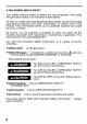
SAFETY SAFETY LABEL LOCATIONS These labels warn you of potential hazards that cancauseserious injury. Read them carefully. If a label comes off or becomes hard to read, contact your Honda generator dealer for a replacement. ISMAllDN SWlTCH I U S IEEN INSTALLED BY A LIUNPD EUCTMCIU. / I DO NOT USE INDOORS.EXHAUST GAS CONTAINS POISONOUS (WARNING CARBON MONOXIDE. I. 2TENc10N ES NE PAS UTlLlSERDANS UN ENOROIT FERME A CAUSE DU RISOUE DEMPOISONNEMENT DU GAZ.
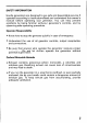
' EM2500X HONDA MOTOR co., LTD. CAUTION 1 MADE IN JAPAN ($ DC WITH RECOMMENDED OIL BEFORE USING. FOR DETAILED EXPLANATION. SEE THE OWNER'S MANUAL. PHASE FREQUENCY RATED OUTPUT 2.3kVA VOLTAGE 12V CURRENT 8.3A GASOLINE FUEL (PETROL) 4 8 I ' E M1800X HONDA MOTOR co., LTD. DC CAUTION BE SURE TO FILL CRANKCASE WITH RECOMMENDED OIL BEFORE USING. FOR DETAILED EXPLANATION, SEE THE OWNER'S MANUAL. \ 6 \ MADE IN JAPAN VOLTAGE FREQUENCY RATED OUTPUT 1.5kVA MAX. OUTPUT 1.
SAFETY INFORMATION Honda generators are designed to give safe and dependable service if operated according to instructions. Read and understand this owner’s manualbeforeoperatingyourgenerator.Youcanhelpprevent accidents by being familiar with yourgenerator’scontrols,andby observing safe operating procedures. Operator Responsibility Know how to stop the generator quickly in case of emergency. Understand the use of all generator controls, output and connections.
~~~ Electric Shock Hazards The generator produces enough electric power shock or electrocution if misused. t o cause a serious Using a generator or electrical appliance in wet conditions, such as rain or snow, or near a pool or sprinkler system, or when your han are wet, could result in electrocution. Keep the generator dry. If the generator is stored outdoors, unprotected from the weather, check all electrical components on the control panel, before each use.
COMPONENT IDENTIFICATION ENGINE SWITCH ~ VOLT METER AIR CLEANER SEDIMENT CUP RECOIL STARTER GRIP DC CIRCUIT PROTECTOR ENGINE SERIAL NUMBER 9
FUEL TANK CAP FUEL METER \ . PLUG CAP \ FRAME SERIAL NUMBER MUFFLER *Record theengine and frameserialnumbersforyourfuture reference. Refer to these serial numbers when ordering parts, and when making technicalor warranty inquiries(see page49 ).
CONTROLS ENGINE SWITCH To start and stop the engine. Switch position: OFF: To stop the engine. ON: To startandruntheengine. ([ [ ON ENGINE SWITCH RECOIL STARTER To start the engine, pull the starter grip lightly until resistance is felt, then pull briskly. riiZEi4 Do not allow the starter grip tosnap back against theengine. Return it gently toprevent damage to the starter.
FUEL VALVE LEVER The fuel valve is located between the fuel tank and carburetor. When the valve lever is in the ON position, fuel is allowed to flow from the to the fuel tank to the carburetor. Be sure to return the fuel valve lever OFF position after stopping the engine. FUEL VALVE LEVER CHOKE LEVER The choke is usedto provide proper starting mixture when the engine iscold. It canbeopenedandclosedbyoperatingthechokelever manually.
AC CIRCUIT BREAKER The AC circuit breaker will automatically switch OFF if there is a short circuit or an overload of the generator at the AC receptacle. If the AC circuit breaker is switched OFF automatically, check that the appliance is working properly and does not exceed the rated load capacityof the AC circuit before switching the AC circuit breaker ON again. The AC circuit breaker may be used to switch the generator AC power ON or OFF.
OIL ALERT@ SYSTEM The Oil Ale& system is designed t o prevent engine damage caused by an insufficient amount of oilin the crankcase. Before the oil level in the crankcase can fall below a safe limit, the Oil Alert? system will automatically stop the engine (the engine switch will remain in theON position). If the engine stops and will not restart, check the engine oil level (see page 23 ) before troubleshooting in otherareas.
VOLT METER The volt meter displays the voltage the generator is producing. VOLTAGE ADJUSTMENT KNOB Although voltage adjustmentis usually not required, fine adjustments may be madebyturningthevoltageadjustmentknob. Use the generator at the specified voltage(1 20 V).
DC TERMINALS The DC terminals may ONLY be used for charging 12 volt automotive type batteries. ( + ) terminal and The terminals are colored red to identify the positive black to identifythenegative (-1 terminal. The batterymust be connectedtothegenerator DC terminalswiththeproperpolarity (battery positive to generator red terminal and battery negative to the generator black terminal).
GENERATOR USE CONNECTIONS TOA BUILDINGELECTRICAL SYSTEM Connections for standby power toa building electrical system must be madebyaqualifiedelectrician.Theconnectionmustisolatethe generatorpowerfromutilitypower,andmustcomplywithall applicable laws and electricalcodes. Improperconnections t o a buildingelectricalsystem can allow electrical current from the generator to backfeed into the utility lines.
AC APPLICATIONS Before connecting an appliance or power cord to the generator: Make sure that it is in good working order. Faulty appliances or power cords cancreate a potential for electricalshock. If an appliance begins to operate abnormally, becomes sluggish or stops suddenly, turn it off immediately. Disconnect the appliance, and determine whether the problem is theappliance, or if the rated load capacity of the generator has been exceeded.
AC OPERATION 1. Start the engine(see page27) and switchON the AC circuit breaker 2. Plug in theappliance. 3. Make sure that the voltmeter indicates the specified voltage. If not, adjust with the voltage adjustment knob. Most motorized appliances require more than their rated wattage for startup. VOLT METER AC CIRCUIT BREAKER VOLTAGE ADJUSTMENT KNOB Ifthegenerator is overloaded,orifthereisashortcircuit in a connected appliance, the AC circuit breaker will automatically switch OFF.
DC OPERATION The DC terminals may ONLY be used for charging12 volt automotive type batteries. Connecting the batterycharging cables: 1. Before connecting the battery charging cable to a battery that installed in a vehicle, disconnect the vehicle ground battery cable from the battery negative ( - ) terminal. A battery can explode if you do not follow the seriously injuring anyone nearby. is correctprocedure, Keep all sparks, open flames, and smoking materials away from the battery. 2.
piEiEil Do notstartthe vehicle while thebatterycharging cables are connected and the generator is running. The vehicle or the generator may bedamaged. An overloaded DC circuit, excessive current draw by the battery, or a wiring problem will trip the DC circuit protector (PUSH button extends out). If this happens, wait a few minutes before pushing in the circuit protector to resume operation. If the circuit protector continues to go OFF, discontinue charging and see your authorized Honda generator dealer.
HIGH ALTITUDE OPERATION At high altitude, the standard carburetor air-fuel mixture will be too rich. Performance will decrease, and fuel consumptionwill increase. A very rich mixture will also foul the spark plug andcause hard starting. Operation at an altitude that differs from that at which this engine was certified, for extended periods of time, may increase emissions. High altitude performance can be improved by specific modifications to the carburetor.
PRE-OPERATION CHECK ENGINE OIL Engine oil is a major factor affecting engine performanceand service life. Non detergent and 2-stroke engine oils will damage the engine and are not recommended. Check the oil level BEFORE EACH USE with the generator on a level surface and the engine stopped. Use 4-stroke motor oil that meets or exceeds the requirements for API serviceclassification SJ. Always check the API SERVICE label on theoilcontainer to besure it inletters the cludes SJ.
REFUELING Fuel tank capacity: 2.91 US gal (11.O 0 ,2.42 Imp gal) With the engine stopped, check the fuel level gauge. Refill the fuel tank if the fuel level is low. Gasoline is highly flammable and explosive.Youcan seriously injured when handlingfuel. be burned or Stop the engineand keep heat, sparks, and flame away. Handle fuelonly outdoors. Wipe upspills immediately. Refuel in a well-ventillated area with the engine stopped.If the engine hasbeenrunning,allow it tocoolfirst.
FUEL RECOMMENDATIONS Use unleaded gasoline witha pump octane rating of 86 or higher. This engine is certified to operate on unleaded gasoline. Unleaded gasoline produces fewer engine and spark plug deposits and extends exhaust system life. Never use stale or contaminated gasoline or an oiVgasoline mixture. Avoid getting dirtor water in the fuel tank. Occasionallyyouma hear a light"sparkknock"or"pinging" (metallic rapping noisewhile operating under heavyloads. This is no cause for concern.
Oxygenated Fuels Some conventional gasolines are being blended with alcohol or an ethercompound. These gasolines are collectivelyreferredto as oxygenated fuels. To meet clean air standards, some areas of the United Statesand Canada use oxygenatedfuelstohelpreduce emissions. If you use an oxygenated fuel, be sure it is unleaded and meets the minimum octane rating requirement. Before using an oxygenated fuel, try to confirm the fuel's contents.
STARTING THE ENGINE STARTING THE ENGINE 1. Make sure that the AC circuit breaker is in the OFF position. The generator may be hard to start aifload is connected. 2. Turn the fuel valve lever to ON theposition. 3. To start a coldengine, move thechoke lever to theCLOSED position. To restart a warm engine, leave the choke lever in the OPEN position. 4. Turn the engine switch to ON the position. 5.Pull the starter grip lightly until resistance is felt, then pull briskly.
STOPPING THE ENGINE STOPPING THE ENGINE To stop the engine in 'an emergency, simply turn the engine switch to the OFF position. Under normal conditions, use the following procedure. 1. Turn theAC circuit breaker to the OFF position. Unplug appliances from the generator AC receptacles. 2. Turn the engine switch to the OFF position. Disconnect DC battery chargingcables (see page 21 ). 3. Turn the fuel valve lever to the OFF position.
THE IMPORTANCE OF MAINTENANCE Good maintenance is essential for safe, economical, and trouble-free operation. It will also help reduceair pollution. Improper maintenance, orfailure t o correct a problembefore operation, can cause amalfunction in which youcan be seriously hurt or killed. Always follow the inspection and maintenance recommendations and schedules in this owner's manual.
MAINTENANCE SAFETY Some of the most important safety precautions follow. However, we cannotwarnyouofeveryconceivable hazard that canarise in performing maintenance. Only you can decide whether or not you should perform a given task. Failure to properly follow maintenance instructions and precautions can causeyou to be seriously hurt or killed. Always followthe procedures and precautions in theowner's manual. Safety Precautions Make sure the engine is off before you begin any maintenance or repairs.
EMISSION CONTROL SYSTEM INFORMATION Source of Emissions Thecombustionprocessproducescarbonmonoxide,oxidesof nitrogen, and hydrocarbons. Control of hydrocarbons and oxides of nitrogenisveryimportant because, undercertainconditions,they react to form photochemical smog when subjected to sunlight. Carbon monoxide does notreact in thesame way, but it is toxic. Honda utilizes lean carburetor settings and other systems the emissions of carbon monoxide, oxides of nitrogen, and hydrocarbons. to reduce The U.S.
Problems That May Affect Emissions If you are aware of any of the following symptoms, have your engine inspected and repaired by your servicing dealer. Hard starting or stalling after starting. Rough idle. Misfiring or backfiring under load. Afterburning (backfiring). Black exhaust smoke or high fuel consumption. Replacement Parts The emission control systems on your Honda engine were designed, built,andcertified toconformwith EPA andCaliforniaemission regulations.
AIR INDEX An Air Index Information hang tag/label is applied to engines certified to an emission durability time period in accordance withthe requirements of the California Air Resources Board. The bar graph is intended to provide you, our customer, the ability to compare the emissions performance of available engines. The lower the AirIndex, the less pollution. The durability description is intendedto provide you with information relating to the engine's emissiondurabilityperiod.
MAINTENANCE SCHEDULE \ REGULAR SERVICEPERIOD (3) ITEM Perform at every indicated month oor p e r a t i n gh o uirn t e r v a l , whichever comes first. I Engine oil Check level Change I Air Check Clean filter First Each use or 20 Hrs. 0 l o Every Every year or or or 300 Hrs. 3 months 6months month 1 0 100 Hrs. I I I I ( 50 Hrs.
ENGINE OIL CHANGE Drain the oil while the engine draining. is warm to assure rapid and complete 1. Remove the oil drain plug and sealing washer, remove the oil filler cap, and drain the oil. OIL DRAIN OIL FILLER CAP PLUG 2.Reinstall the oil drain plug and sealing washer. Tighten the plug securely. 3. Refill with the recommended oil level. (see page 23 ) and check the oil Oil capacity: 0.63US qt (0.60 !2,0.53Imp qt) 4.
AIR CLEANER SERVICE A dirty air cleaner will restrict air flow to the carburetor. To prevent carburetor malfunction, service the air cleaner regularly. Service more frequently when operating the generator in extremely dusty areas. Using gasoline orflammable solvent to clean the air filter can cause a fire or explosion. Use only soapy water or nonflammable solvent. 1 NOTICE Never run the generator without the air filter. Rapid engine wear will result. 1.
FUEL SEDIMENT CUP CLEANING The sediment cup prevents dirt or water which may in bethe fuel tank from entering the carburetor. If the engine has not been run fora long time, the sediment cup should be cleaned. 1. Turn the engine switch to OFF the position. 2. Turn the fuel valve lever to OFF the position. 3. Remove the sediment cup by turning it counterclockwise. 4.Clean the sediment cup and O-ring point solvent. in nonflammable or high flash 5. Reinstall the O-ring and sediment cup. 6.
SPARK PLUG SERVICE In order to service the spark plug, you will needa spark plug wrench (commercially available). Recommended spark plugs: BPRGES (NGK) W20EPR-U (DENSO) TO ensure proper engine operation, the spark plug must gapped and free of deposits. be properly If the engine has been running, the muffler willbe very hot. Be careful not to touch the muffler. 1. Remove the spark plugcap. 2. Clean any dirt from around t h e spark plug base. 3. Use a spark plug wrench to remove the spark plug.
6. Check that the spark plug washer is in good condition, and thread the spark plug in byhand to prevent cross-threading. 7.After the spark plug is seated, tighten with a spark plug wrench to compress the washer. If installing a new spark plug, tighten 1/2 turn after the spark plug If reinstallingausedsparkplug, seats tocompressthewasher. tighten 1/8-1/4 turn after the spark plug seats to compressthe washer. m The spark plug must besecurely tightened.
SPARK ARRESTER MAINTENANCE If the generatorhas been running, the muffler willbe very hot. Allow it to cool before proceeding. The spark arrester must efficiency. be serviced every 100 hours to maintain its Clean the spark arresteras follows: 1. Remove the five6 m m bolts, and remove the muffler protector. MUFFLER PROTECTOR 2. h m o v e the two 8 mm bolts a t the exhaust pipe and 8 mm bolt at the muffler stay. Remove the muffler and spark arrester.
3. Usea brush to remove carbon deposits from the spark arrester screen. 4. Inspect thescreen for breaks or tears and replace it if necessary. 5.Check the muffler gasket; replace if damaged. Reinstall the muffler gasket, the spark arrester, the muffler and the muffler protector in the reverse order of removal.
TRANSPORTIMG/STORAGE TRANSPORTING If the generator has been used, allow it cool for a t least 15 minutes before loading the generator on the transport vehicle. A hot engine and exhaust system can burn you and can ignite some material. When transporting the generator, turn the engine switch and the fuel valve lever OFF, and keep the generator level to reduce the possibility of fuelleakage. Take care not to drop or strike the generator when transporting. Do not place heavy objects on the generator.
STORAGE Before storing the unit for an extended period: 1. Be sure the storagearea is free ofexcessive humidity and dust. 2. Service according to the table below: RECOMMENDED SERVICEPROCEDURE TO PREVENT HARDSTARTING Less than 1 month No preparation required 1 to 2 months Fill with freshgasolineandaddgasoline conditioner *. Fill with freshgasolineandaddgasoline 2 months to1 year conditioner *. Drain the carburetor float bowl. (page 44). Drain the fuel sediment cup. (page 37).
Storage Procedure 1.Drain the fuel tank, the carburetor and the fuel sediment cup. a. Removethe carburetor drain screw. b.Drain the gasoline from the carburetor into a suitable container. c. Install and tighten the carburetor drain screw. d.Turn the fuel valve lever off and drain the fuel sediment cup. e.Turn the fuel valve lever on anddrain the gasoline from the fuel tank into a suitable container. f. Install and tighten the fuel sediment cup securely. g.Turn the fuel valve lever off.
Add TROUBLESHOOTING When the enginewill not start: ~ Is there fuel in the tank? NO Refill the fueltank. IYES oil enough Is there in I YES Is there spark a f r o mt h es p a r k plug? - Still NO spark NO R e p l a c et h e sparkplug. Be sure there is no spilled fuel around the spark plug. Spilled fuel may ignite. YES 1 Is the fuel reaching NO the carburetor? YES t Iftheenginestill does not start, take the generator to an authorized Honda generator dealer.
Appliance does notoperate: Is the AC circuit breaker ON? NO Turnthe AC circuit breaker ON. NO DEFECTS Check the electrical appiance or equipment for any defects. Take thegeneratorto an authorizedHondagenerator dealer. Replace the electrical appliance or equipment. .Take the electrical ap- DEFECTS pliance or e q u i p m e n t to a n electrical shop for repair. No electricity at theDC terminals: Is the DC circuit protector Turn the DC circuit protector on.
CONTROL BOX BLOCK - 1 - ;ROUND TERMlNlAL I 4 OIL LEVEL SWITCH I .
SPECIFICATIONS Dimensions Model Power product description code Length Width Height Dry weight EM1800X EM2500X EZCK EZCN 19.9 in (505 mm) 16.5 in (420 m m ) 16.5 in (420 mm) 91.5 Ibs (41.5 kg) I 98.1 Ibs (44.5 kg) Engine Model Engine Type Displacement [Bore x Stroke] Compression Ratio Engine Speed Cooling System Ignition System Oil Capacity Fuel Tank Capacity Spark Plug GX160K1 4-stroke, overhead valve, single cylinder 9.9 cu-in (163 cm3) (2.7 X 1.8 in (68 X 45 mm)] 8.
WARRANTY SERVICE INFORMATION Servicing dealership personnelare trained professionals. They should be able to answer any question you may have. If you encounter a problem that your dealer does not solve to your satisfaction, please discuss it with the dealership's management. The Service Manager or General Manager can help. Almost all problems are solved in this way. If you. aredissatisfied with thedecisionmade by thedealership's management, contact the Honda Power Equipment Customer Relations Office.
INDEX COMPONENT IDENTIFICATION ............................................................... 9 CONTENTS ................................................................................................. 3 CONTROLS ............................................................................................... 11 AC Circuit Breaker ............................................................................... 13 12 Choke Lever .................................................................................
SAFETY ....................................................................................................... Safety Information ............................................................................... Safety Label Locations ........................................................................ SPECIFICATIONS ..................................................................................... STARTING THE ENGINE .........................................................................
MEMO 52