EM3800SX•EM5000SX•EM6500SX K2:EM5000SX 31Z21600 00X31-Z21-6000 See page 54 for instructions on assembling your generator.
03/11/17 18:38:36 31Z21600_001 The engine exhaust from this product contains chemicals known to the State of California to cause cancer, birth defects or other reproductive harm. The generator is a potential source of electrical shock if misused. Do not expose the generator to moisture, rain or snow. Do not let the generator get wet, and do not operate it with wet hands. Keep this owner’s manual handy, so you can refer to it at any time.
03/11/17 18:38:42 31Z21600_002 Congratulations on your selection of a Honda generator. We are certain you will be pleased with your purchase of one of the finest generators on the market. We want to help you get the best results from your new generator and to operate it safely. This manual contains the information on how to do that; please read it carefully. As you read this manual, you will find information preceded by a symbol.
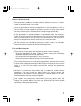
03/11/17 18:38:55 31Z21600_003 A FEW WORDS ABOUT SAFETY Your safety and the safety of others are very important. And using this generator safely is an important responsibility. To help you make informed decisions about safety, we have provided operating procedures and other information on labels and in this manual. This information alerts you to potential hazards that could hurt you or others.
03/11/17 18:39:00 31Z21600_004 CONTENTS SAFETY ....................................................................................................... 5 Safety Label Locations ........................................................................ 5 Safety Information ............................................................................... 6 COMPONENT IDENTIFICATION ............................................................... 8 CONTROLS ...........................................................
03/11/17 18:39:02 31Z21600_005 TRANSPORTING/STORAGE ................................................................... 44 TROUBLESHOOTING .............................................................................. 47 WIRING DIAGRAM .................................................................................. 49 SPECIFICATIONS ..................................................................................... 51 ASSEMBLY ............................................................................
03/11/17 18:39:14 31Z21600_006 SAFETY SAFETY LABEL LOCATIONS These labels warn you of potential hazards that can cause serious injury. Read them carefully. If a label comes off or becomes hard to read, contact your Honda generator dealer for a replacement.
03/11/17 18:39:22 31Z21600_007 SAFETY INFORMATION Honda generators are designed to give safe and dependable service if operated according to instructions. Read and understand this owner’s manual before operating your generator. You can help prevent accidents by being familiar with your generator’s controls, and by observing safe operating procedures. Operator Responsibility Know how to stop the generator quickly in case of emergency.
03/11/17 18:39:32 31Z21600_008 Electric Shock Hazards The generator produces enough electric power to cause a serious shock or electrocution if misused. Using a generator or electrical appliance in wet conditions, such as rain or snow, or near a pool or sprinkler system, or when your hands are wet, could result in electrocution. Keep the generator dry. If the generator is stored outdoors, unprotected from the weather, check all of the electrical components on the control panel, before each use.
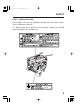
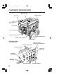
03/11/17 18:39:39 31Z21600_009 COMPONENT IDENTIFICATION ENGINE SWITCH CONTROL PANEL CHOKE ROD AIR CLEANER FUEL VALVE LEVER RECOIL STARTER GRIP OIL FILTER CAP/DIP STICK ENGINE SERIAL NUMBER FUSE OIL DRAIN BOLT CONTROL PANEL * 1:Except EM3800SX 120 ONLY−120/240 VOLTAGE SELECTOR SWITCH AC CIRCUIT PROTECTORS AC CIRCUIT BREAKER 120/240 AC RECEPTACLE DC CIRCUIT PROTECTOR * 1 DC OUTPUT TERMINAL AUTO THROTTLE AC RECEPTACLES SWITCH 8 GROUND TERMINAL
03/11/17 18:39:56 31Z21600_011 CONTROLS Engine Switch To start and stop the engine. Key position: OFF: To stop the engine. Key can be removed/inserted. ON: To run the engine after starting. START: To start the engine by operating the starter motor. OFF ON START ENGINE SWITCH Recoil Starter To start the engine, pull the starter grip lightly until resistance is felt, then pull briskly. Do not allow the starter grip to snap back against the engine. Return it gently to prevent damage to the starter.
03/11/17 18:40:02 31Z21600_012 Fuel Valve Lever The fuel valve is located between the fuel tank and carburetor. When the valve lever is in the ON position, fuel is allowed to flow from the fuel tank to the carburetor. Be sure to return the fuel valve lever to the OFF position after stopping the engine. FUEL VALVE LEVER OFF ON Choke Rod The choke is used to provide an enriched fuel mixture when starting a cold engine. It can be opened and closed by operating the choke rod manually.
03/11/17 18:40:11 31Z21600_013 Voltage Selector Switch (Dual Voltage System) The voltage selector switch switches the main power carrying windings of the generator to produce ‘‘120V ONLY’’ or ‘‘120/240V’’. If a 240V appliance is connected to the 4-prong receptacle, the switch must be in the ‘‘120/240V’’ position. If only a 120V appliance is being connected to any of the 120V 3-prong receptacles, select the ‘‘120V ONLY’’ position.
03/11/17 18:40:17 31Z21600_014 DC Terminals The DC terminals may ONLY be used for charging 12 volt automotive type batteries. The terminals are colored red to identify the positive (+) terminal and black to identify the negative (−) terminal. The battery must be connected to the generator DC terminals with the proper polarity (battery positive to generator red terminal and battery negative to the generator black terminal).
03/11/17 18:40:26 31Z21600_015 Oil Alert System The Oil Alert system is designed to prevent engine damage caused by an insufficient amount of oil in the crankcase. Before the oil level in the crankcase can fall below a safe limit, the Oil Alert system will automatically stop the engine (the engine switch will remain in the ON position). The Oil Alert system should not take the place of checking the oil level before each use.
03/11/17 18:40:31 31Z21600_016 AC Circuit Breaker The AC circuit breaker will automatically switch OFF if there is a short circuit or a significant overload of the generator at the receptacle. If the AC circuit breaker is switched OFF automatically, check that the appliance is working properly and does not exceed the rated load capacity of the circuit before switching the AC circuit breaker ON again. The AC circuit breaker may be used to switch the generator power ON or OFF.
03/11/17 18:40:35 31Z21600_017 AC Circuit Protector The AC circuit protectors will automatically switch OFF if there is a short circuit or a significant overload of the generator at the 20A 120V, 30A 120V locking plug, or 120/240V locking plug receptacle. If a AC circuit protector switches OFF automatically, check that the appliance is working properly and does not exceed the rated load capacity of the circuit before resetting the AC circuit protector ON.
03/11/17 18:40:44 31Z21600_018 GENERATOR USE Connections to a Building Electrical System Connections for standby power to a building electrical system must be made by a qualified electrician. The connection must isolate the generator power from utility power, and must comply with all applicable laws and electrical codes. A transfer switch, which isolates generator power from utility power, is available through authorized Honda generator dealers.
03/11/17 18:40:55 31Z21600_019 AC Applications Before connecting an appliance or power cord to the generator: Make sure that it is in good working order. Faulty appliances or power cords can create a potential for electrical shock. If an appliance begins to operate abnormally, becomes sluggish or stops suddenly, turn it off immediately. Disconnect the appliance, and determine whether the problem is the appliance, or if the rated load capacity of the generator has been exceeded.
03/11/17 18:41:04 31Z21600_020 AC Operation 1. Start the engine (see page 30 ). 2. Turn the voltage selector switch to either position. With the voltage selector switch in the ‘‘120/240V’’ position, you can use the 120V and 120/240V receptacles simultaneously. If you are NOT using the 120/240V receptacle, but require more power from the 120V locking plug receptacle, then select the ‘‘120V ONLY’’ position. 3. Switch the AC circuit breaker ON. 4. Plug in the appliance.
03/11/17 18:41:14 31Z21600_021 AC Receptacle Selection EM3800SX: The generator has two separate main power producing circuits. These two circuits supply equal power to different receptacles shown when the voltage selector switch is in the 120/240V position. When two or more receptacles are used; prevent overloading by dividing the load between the two power circuits. The chart below shows the rated load in amperes that can be connected to each receptacle to balance the generator.
03/11/17 18:41:23 31Z21600_022 EM5000SXK2: The generator has separate main power producing circuits. These two circuits supply equal power to different receptacles shown when the voltage selector switch is in the 120/240V position. When two or more receptacles are used; prevent overloading by dividing the load between the two power circuits. The chart below shows the rated load in amperes that can be connected to each receptacle to balance the generator. The total rated ampere draw is 37.5A.
03/11/17 18:41:31 31Z21600_023 EM6500SX: The generator has separate main power producing circuits. These two circuits supply equal power to different receptacles shown when the voltage selector switch is in the 120/240V position. When two or more receptacles are used; prevent overloading by dividing the load between the two power circuits. The chart below shows the rated load in amperes that can be connected to each receptacle to balance the generator. The total rated ampere draw is 45.8A.
03/11/17 18:41:42 31Z21600_024 DC Operation The DC terminals may ONLY be used for charging 12 volt automotive type batteries. Connecting the battery cables: 1. Before connecting the battery charging cables to a battery that is installed in a vehicle, disconnect the vehicle ground battery cable from the battery negative (−) terminal. The battery gives off explosive gases; keep sparks, flames and cigarettes away. Provide adequate ventilation when charging or using batteries.
03/11/17 18:41:51 31Z21600_025 An overloaded DC circuit, excessive current draw by the battery, or a wiring problem will trip the DC circuit protector (PUSH button extends out). If this happens, wait a few minutes before pushing in the circuit protector to resume operation. If the DC circuit protector continues to go OFF, discontinue charging and see your authorized Honda generator dealer. Disconnecting the battery cables: 1. Stop the engine. 2.
03/11/17 18:41:58 31Z21600_026 Auto Throttle System With the switch in the AUTO position, engine speed is automatically reduced when ALL loads are turned OFF or disconnected. When appliances are turned ON or reconnected, the engine returns to rated speed. In the OFF position, the auto throttle system does not operate. The auto throttle system will not respond to electrical loads of less than 1 ampere or intermittent loads such as a staple gun.
03/11/17 18:42:04 31Z21600_027 High Altitude Operation At high altitude, the standard carburetor air/fuel mixture will be too rich. Performance will decrease, and fuel consumption will increase. A very rich mixture will also foul the spark plug and cause hard starting. Operation at an altitude that differs from that at which this engine was certified, for extended periods of time, may increase emissions. High altitude performance can be improved by specific modifications to the carburetor.
03/11/17 18:42:16 31Z21600_028 PRE-OPERATION CHECK Engine Oil Engine oil is a major factor affecting engine performance and service life. Non detergent and 2-stroke engine oils will damage the engine and are not recommended. Check the oil level BEFORE EACH USE with the generator on a level surface and the engine stopped. Use 4-stroke motor oil that meets or exceeds the requirements for API service classification SJ.
03/11/17 18:42:26 31Z21600_029 Fuel Check the fuel gauge, and refill the tank if the fuel level is low. Refuel carefully to avoid spilling fuel. Do not fill above the shoulder of the fuel strainer. Gasoline is highly flammable and explosive, and you can be burned or seriously injured when refueling. Stop engine and keep heat, sparks, and flame away. Refuel only outdoors. Wipe up spills immediately. Fuel tank capacity: 6.
03/11/17 18:42:40 31Z21600_030 Occasionally you may hear a light ‘‘spark knock’’ or ‘‘pinging’’ (metallic rapping noise) while operating under heavy loads. This is no cause for concern. If spark knock or pinging occurs at a steady engine speed, under normal load, change brands of gasoline. If spark knock or pinging persists, see an authorized Honda generator dealer. Running the engine with persistent spark knock or pinging can cause engine damage.
03/11/17 18:42:57 31Z21600_031 STARTING THE ENGINE/STOPPING THE ENGINE Starting the Engine 1. Make sure that the AC circuit breaker is in the OFF position. The generator may be hard to start if a load is connected. 2. Turn the fuel valve lever to the ON position. 3. The automatic choke will be closed if the engine is cold. If you want to operate the choke manually, pull the choke rod out to the CLOSED position. 4.
03/11/17 18:43:04 31Z21600_032 MAINTENANCE The Importance of Maintenance Good maintenance is essential for safe, economical, and trouble-free operation. It will also help reduce air pollution. Improper maintenance, or failure to correct a problem before operation, can cause a malfunction in which you can be seriously hurt or killed. Always follow the inspection and maintenance recommendations and schedules in this owner’s manual.
03/11/17 18:43:15 31Z21600_033 Maintenance Safety Some of the most important safety precautions follow. However, we cannot warn you of every conceivable hazard that can arise in performing maintenance. Only you can decide whether or not you should perform a given task. Failure to properly follow maintenance instructions and precautions can cause you to be seriously hurt or killed. Always follow the procedures and precautions in the owner’s manual.
03/11/17 18:43:24 31Z21600_034 Emission Control System Information Source of Emissions The combustion process produces carbon monoxide, oxides of nitrogen, and hydrocarbons. Control of hydrocarbons and oxides of nitrogen are very important because, under certain conditions, they react to form photochemical smog when subjected to sunlight. Carbon monoxide does not react in the same way, but it is toxic.
03/11/17 18:43:28 31Z21600_035 Problems That May Affect Emissions If you are aware of any of the following symptoms, have your engine inspected and repaired by your servicing dealer. Hard starting or stalling after starting. Rough idle. Misfiring or backfiring under load. Afterburning (backfiring). Black exhaust smoke or high fuel consumption.
03/11/17 18:43:33 31Z21600_036 Replacement Parts The emission control systems on your Honda engine were designed, built, and certified to conform with EPA and California emission regulations. We recommend the use of genuine Honda parts whenever you have maintenance done. These original-design replacement parts are manufactured to the same standards as the original parts, so you can be confident of their performance.
03/11/17 18:43:44 31Z21600_037 Air Index An Air Index Information hang tag/label is applied to engines certified to an emission durability time period in accordance with the requirements of the California Air Resources Board. The bar graph is intended to provide you, our customer, the ability to compare the emissions performance of available engines. The lower the Air Index, the less pollution.
03/11/17 18:43:58 31Z21600_038 Maintenance Schedule REGULAR SERVICE PERIOD (3) ITEM Performed at every indicated month or operating hour interval, whichever comes first. Engine oil Air cleaner Sediment cup Spark plug Spark arrester Idle speed Valve clearance Combustion chamber Fuel tank and filter Fuel tube Check Change Check Clean Clean Clean-Adujst Replace Clean Check-Adujst Check-Adujst Clean Clean Check Before each use First month or 20 Hrs. Every Every Every 3 months 6 months year or or or 50 Hrs.
03/11/17 18:44:08 31Z21600_039 Engine Oil Change Drain the oil while the engine is warm to assure rapid and complete draining. 1. Remove the drain plug and sealing washer, remove the oil filler cap, and drain the oil. 2. Reinstall the drain plug and sealing washer. Tighten the plug securely. 3. Refill with the recommended oil (see page 27 ) and check the oil level. Oil capacity: 1.2 US qt (1.1 ) UPPER LEVEL OIL DRAIN PLUG Wash your hands with soap and water after handling used oil.
03/11/17 18:44:19 31Z21600_040 Air Cleaner Service A dirty air cleaner will restrict air flow to the carburetor. To prevent carburetor malfunction, service the air cleaner regularly. Service more frequently when operating the generator in extremely dusty areas. Never run the generator without the air filter. Rapid engine wear will result. 1. Unsnap the air cleaner cover clips, remove the air cleaner cover, and remove the element. 2.
03/11/17 18:44:26 31Z21600_041 Fuel Sediment Cup Cleaning The sediment cup prevents dirt or water which may be in the fuel tank from entering the carburetor. If the engine has not been run for a long time, the sediment cup should be cleaned. 1. Turn the fuel valve lever to the OFF position. Remove the sediment cup, O-ring, and filter. 2. Clean the sediment cup, O-ring, and filter in nonflammable or high flash point solvent. 3. Reinstall the filter, O-ring, and sediment cup. 4.
03/11/17 18:44:37 31Z21600_042 Spark Plug Service In order to service the spark plug, you will need a spark plug wrench (commercially available). Recommended spark plugs: BPR5ES (NGK) , W16EPR-U (DENSO) To ensure proper engine operation, the spark plug must be properly gapped and free of deposits. If the engine has been running, the muffler will be very hot. Be careful not to touch the muffler. 1. Remove the spark plug cap. 2. Clean any dirt from around the spark plug base. 3.
03/11/17 18:44:51 31Z21600_043 6. Check that the spark plug washer is in good condition, and thread the spark plug in by hand to prevent cross-threading. 7. After the spark plug is seated, tighten with a spark plug wrench to compress the washer. −If installing a new spark plug, tighten 1/2 turn after the spark plug seats to compress the washer. If reinstalling a used spark plug, tighten 1/8−1/4 turn after the spark plug seats to compress the washer. The spark plug must be securely tightened.
03/11/17 18:44:57 31Z21600_044 Fuse Replacement If the fuse is blown, the starter motor won’t operate. 1. Turn the engine switch to the OFF position. 2. Remove the fuse holder cover and replace the fuse. The specified fuse is 10A. FUSE HOLDER If frequent fuse failure occurs, determine the cause and correct the problem before attempting to operate the generator further. Never use a fuse with a different rating from that specified. Serious damage to the electrical system or fire may result.
03/11/17 18:45:03 31Z21600_045 TRANSPORTING/STORAGE When transporting the generator, turn the engine switch and the fuel valve OFF. Keep the generator level to prevent fuel spillage. Fuel vapor or spilled fuel may ignite. Contact with a hot engine or exhaust system can cause serious burns or fires. Let the engine cool before transporting or storing the generator. Take care not to drop or strike the generator when transporting. Do not place heavy objects on the generator.
03/11/17 18:45:08 31Z21600_046 Before storing the unit for an extended period: 1. Be sure the storage area is free of excessive humidity and dust. 2. Service according to the table below: STORAGE TIME RECOMMENDED SERVICE PROCEDURE TO PREVENT HARD STARTING Less than 1 month No preparation required 1 to 2 months Fill with fresh gasoline and add gasoline conditioner *. Fill with fresh gasoline and add gasoline 2 months to 1 year conditioner *. Drain the carburetor float bowl. (page 46 ).
03/11/17 18:45:17 31Z21600_047 Storage 1. Drain the carburetor by loosening the drain screw. Drain the gasoline into a suitable container. Gasoline is extremely flammable and is explosive under certain conditions. Perform this task in a well-ventilated area with the engine stopped. Do not smoke or allow flames or sparks in the area during this procedure. DRAIN SCREW 2. Change the engine oil (page 38 ). 3. Remove the spark plug, and pour about a tablespoon of clean engine oil into the cylinder.
03/11/17 18:45:26 31Z21600_048 TROUBLESHOOTING When the engine will not start: Is there fuel in the tank? NO Refill the fuel tank. YES Is there enough oil NO in the engine? Add the recommended oil. YES Is the spark plug in NO good condition? Readjust gap and dry the spark plug. Replace it if necessary. YES Is the fuel reaching NO the carburetor? YES If the engine still does not start, take the generator to an authorized Honda generator dealer. Clean the fuel sediment cup.
03/11/17 18:45:30 31Z21600_049 No electricity at the AC receptacles: Is the AC circuit breaker ON. YES Turn the AC circuit breaker ON. NO DEFECTS Check the electrical appliance or equipment for any defects. DEFECTS 48 NO Take the generator to an authorized Honda generator dealer. Replace the electrical appliance or equipment. Take the electrical appliance or equipment to an electrical shop for repair.
03/11/17 18:45:59 31Z21600_050 WIRING DIAGRAM EM3800SX 49
03/11/17 18:46:27 31Z21600_051 EM5000SX, EM6500SX 50
03/11/17 18:46:43 31Z21600_052 SPECIFICATIONS Dimensions Model Power product description code Length Width Height Dry weight EM3800SX EAMC 40.9 in (1,040 mm) 27.2 in (690 mm) 28.3 in (720 mm) 192 lbs (87 kg) Engine Model Engine Type Displacement Bore × Stroke Compression Ratio Engine Speed Cooling System Ignition System Oil Capacity Fuel Tank Capacity Spark Plug GX240 4-stroke, overhead valve, single cylinder 14.8 cu-in (243 cm ) 2.9 × 2.3 in (73 × 58 mm) 8.
03/11/17 18:46:58 31Z21600_053 Dimensions Model Power product description code Length Width Height Dry weight EM5000SXK2 EANC 41.3 in (1,050 mm) 27.2 in (690 mm) 28.3 in (720 mm) 223 lbs (101 kg) Engine GX340 Model Engine Type Displacement Bore × Stroke Compression Ratio Engine Speed Cooling System Ignition System Oil Capacity Fuel Tank Capacity Spark Plug 4-stroke, overhead valve, single cylinder 20.6 cu-in (338 cm ) 3.2 × 2.5 in (82 × 64 mm) 8.
03/11/17 18:47:17 31Z21600_054 Dimensions Model Power product description code Length Width Height Dry weight EM6500SX EAPC 41.9 in (1,065 mm) 27.2 in (690 mm) 28.3 in (720 mm) 227 lbs (103 kg) Engine GX390 Model Engine Type Displacement Bore × Stroke Compression Ratio Engine Speed Cooling System Ignition System Oil Capacity Fuel Tank Capacity Spark Plug 4-stroke, overhead valve, single cylinder 23.7 cu-in (389 cm ) 3.5 × 2.5 in (88 × 64 mm) 8.
03/11/17 18:47:23 31Z21600_055 ASSEMBLY The Importance of Proper Assembly Proper assembly is essential to operator safety and the reliability of the machine. Any error or oversight made by the person assembling and servicing a unit can easily result in faulty operation, damage to the machine, or injury to the operator. Improper assembly can cause an unsafe condition that can lead to serious injury or death. Follow the procedures and precautions in the assembly instructions carefully.
03/11/17 18:47:31 31Z21600_056 Important Safety Precautions Make sure you have a clear understanding of all basic shop safety practices and that you are wearing appropriate clothing and safety equipment. When performing this assembly, be especially careful of the following: □ Read the instructions before you begin and be sure you have the tools and skills required to perform the tasks safely. Make sure the engine is off before you begin any maintenance or repairs.
03/11/17 18:47:43 31Z21600_057 Unpacking 1. Remove the generator and loose parts box from the carton. 2. Compare the loose parts with the inventory list below. Tools Required: 14 mm wrench (2), pliers Loose Parts (Wheel kit and handle) Check all loose parts against the following list. Contact your dealer if any of the loose parts shown below are not included with your generator. Ref. No.
03/11/17 18:47:48 31Z21600_058 Handle Installation Install the right and left handles on the generator upper frame using the brackets and 4 flange bolts. TORQUE: 17−22 lbf·ft (24−29 N·m , 2.4−3.
03/11/17 18:47:57 31Z21600_059 Wheel Kit Installation 1. Install the two wheels on the axle shaft using the washers and cotter pins. 2. Install the axle assembly on the generator using four 8 × 16 mm flange bolts and 8 mm flange nuts. 3. Install the two stands on the under frame using four 8 × 16 mm flange bolts. TORQUE: 17−22 lbf·ft (24−29 N·m , 2.4−3.0 kgf·m) GENERATOR SIDE 8×16 mm FLANGE BOLT (4) LONGER 8×16 mm FLANGE BOLT (4) AXLE WHEEL (2) 20 mm WASHER (2) STAND (2) 4.
03/11/17 18:48:03 31Z21600_060 Hanger Kit Installation (optional) 1. Position the hanger at the generator’s balance point as shown below. 2. Fit the end tabs of the hanger through the bracket slots, and bolt the brackets to the hanger and tighten securely. TORQUE: 17−22 lbf·ft (24−29 N·m , 2.4−3.
03/11/17 18:48:10 31Z21600_061 Remote Control Kit (optional) 1. Remove the blind 6-P connector from the back of the control panel. 2. Connect the remote control cable to the back of the control panel and remote control box. 3. Install the two cable ties as shown. REMOTE CONTROL CABLE CABLE TIES REMOTE CONTROL CABLE REMOTE CONTROL BOX Connect the blind connector when not using the remote control. Engine will not start unless the blind connector is connected.
03/11/17 18:48:21 31Z21600_062 Remote Control Box PILOT LAMP START SWITCH STOP SWITCH Starting the engine with remote control 1. Turn the fuel valve to the ON position. 2. Turn the auto-throttle switch to the OFF position. 3. Turn the engine switch to the ON position. 4. Press the start switch untill the pilot lamp comes on. Stopping the engine with remote control 1. Press the stop switch. 2. Turn the engine switch to the OFF position. 3. Turn the fuel valve lever to the OFF position.
03/11/17 18:48:25 31Z21600_063 Battery Tray Kit (optional) 1. Install the battery guard on the frame. Set the battery tray on the battery guard and tighten the bolts. 2. Route the starter cable under the tank and connect it to the starter solenoid. 3. Connect the ground cable to the generator rear housing. 4. Set the battery on the battery tray and secure with the battery bracket. Connect the starter cable to the battery positive (+) terminal first, then to the negative (−) terminal.
03/11/17 19:47:49 31Z21600_064 CABLE TIE STARTER SOLENOID STARTER CABLE (positive) GROUND CABLE STARTER CABLE BATTERY BRACKET CABLE TIE GROUND CABLE BATTERY Use a battery rated at 51R + ○ − ○ BATTERY GUARD BATTERY GUARD BATTERY TRAY BATTERY GUARD PLATE 63
03/11/17 18:48:44 31Z21600_065 Engine Oil The generator is shipped WITHOUT OIL in the engine. SAE Viscosity Grades Place the generator on a level surface. Add enough of the recommended oil to bring the oil level to the top of the oil filler neck. Use a 4-stroke motor oil that meets the requirements for API service classification SJ. AMBIENT TEMPERATURE OIL FILLER HOLE SAE 10W-30 is recommended for general, all-temperature use.
03/11/17 18:48:51 31Z21600_066 BEFORE OPERATION Before using your generator, you should become familiar with information contained in the following chapters and sections: SAFETY (page 5 ) CONTROLS (page 10 ) GENERATOR USE (page 17 ) STARTING THE ENGINE (page 30 ) STOPPING THE ENGINE (page 30 ) 65
03/11/17 18:48:59 31Z21600_067 WARRANTY SERVICE INFORMATION Servicing dealership personnel are trained professionals. They should be able to answer any questions you may have. If you encounter a problem that your dealer does not solve to your satisfaction, please discuss it with the dealership’s management. The Service Manager or General Manager can help. Almost all problems are solved in this way.
03/11/17 18:49:03 31Z21600_068 INDEX ASSEMBLY ............................................................................................... 54 COMPONENT IDENTIFICATION ............................................................... 8 CONTENTS ................................................................................................. 3 CONTROLS ............................................................................................... 10 AC Circuit Breaker .......................................
03/11/17 18:49:06 31Z21600_069 PRE-OPERATION CHECK ........................................................................ 27 Engine Oil ........................................................................................... 27 Fuel ...................................................................................................... 28 SAFETY ....................................................................................................... 5 Safety Information ...................................
EM3800SX•EM5000SX•EM6500SX K2:EM5000SX 31Z21600 00X31-Z21-6000 See page 54 for instructions on assembling your generator.