Owner's Manual SNOWBLOWER HS622 ©1996 Honda Motor Co., Ltd.
The engine exhaust from this product contains chemicals known to the State of California to cause cancer, birth defects or other reproductive harm.
Thank you for purchasing a Honda snowblower. We want to help you get the best results from your new snowblower and to operate it safely. This manual contains the information on how to do that; please read it carefully. This owner’s manual describes the operation and maintenance of HONDA snowblower: HS622 All information in this publication is based on the latest product information available at the time of printing. Honda Motor Co., Ltd.
CONTENTS 3 SAFETY ........................................................................................................ 3 .................................................................. SAFETY LABEL LOCATIONS 4 .......................................................................... SAFETY INFORMATION .7 COMPONENT IDENTIFICATION.. .............................................................. 8 ..................................................................................................
SAFETY SAFETY LABEL LOCATIONS These labels warn you of potential injury. Read them carefully. hazards that can cause If a label comes off or becomes hard to read, contact Snowblower dealer for a replacement.
SAFETY INFORMATION Most accidents with snowblowers can be prevented if you follow all instructions in this manual and on the snowblower. The most common hazards are discussed below, along with the best way to protect yourself and others. Always make a pre-operation check (pages 14 thru 18 ) before you start the engine. You may prevent an accident or equipment damage. Honda snowblowers are designed to give safe and dependable service if operated according to instructions.
l l l l l l Adjust the snow discharge chute to avoid hitting the operator, bystanders, windows, and other objects with ejected snow. Stay clear of the snow discharge chute while the engine is running. Children and pets must be kept away from the area of operation avoid injury from flying debris and contact with the snowblower. to To avoid overturning, be careful when changing the direction of the snowblower while operating it on a slope. Do not use the snowblower to remove snow from roofs.
l l l l l Gasoline is extremely conditions. flammable certain Do not overfill the fuel tank, and make sure the filler cap is closed securely after refueling. Never run the engine in an enclosed or confined area. Exhaust contains poisonous carbon monoxide gas; exposure can cause loss of consciousness and may lead to death. The muffler becomes very hot during operation after stopping muffler while it is hot. snowblower indoors.
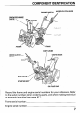
COMPONENT IDENTIFICATION ENGINE SWITCH AUG/ER CLUTCH LEVER SNOW CHUTE SHIFT LEVER CHUTE GUIDE / FUEL VALVE STARTER GRIP OIL FILLER CAP Record the frame and engine serial numbers for your reference. Refer to the serial numbers when ordering parts, and when making technical or warranty inquiries (see page 47 ).
CONTROLS Engine Switch Use the engine switch to STOP the engine. to turn the ignition system ON for starting, and ENGINE SWITCH Fuel Valve The fuel valve opens and closes the fuel line leading from the fuel tank to the carburetor. Make sure that the valve is positioned exactly at either the ON or OFF position. When the snowblower is not in use, always leave the fuel valve in the OFF position to reduce the possibility of fuel leakage.
Choke Lever Close the choke when the engine is cold or difficult to start. Starter Grip See page 19 for starting procedures. Pull this grip to start the engine.
Throttle Lever Use the throttle lever to select engine the “FAST” position. speed. In normal THROlTLE operation, LEVER Shift Lever Use the shift lever to select drive speed or direction.
Chute Guide The chute guide controls the snow discharge angle and direction. CHUTE GUIDE CHUTE GUIDE Drive Clutch Lever Use the drive clutch lever to propel or stop the snowblower.
Auger Clutch Lever Squeezing the auger clutch lever also operates the drive clutch lever; the snowblowing mechanism starts and the snowblower moves forward. Releasing the auger clutch lever stops both the snowblowing mechanism and the forward motion of the snowblower. STOP Height Adjustment AUGER CLUTCH LEVER Bolt Use the bolt for adjusting relation to the tracks.
Skid Plate and Scraper Adjust the skid plates and scraper for the auger housing ground clearance best suited to your snow removal conditions. (See page 22 ) / SCRAPER Handle Height Adjusting Bolt The handlebars can be set in the high, low or middle position to suit the operator. To change handlebar height, remove the right and left adjusting bolts, align the bolt holes for the desired handlebar height, and reinstall the bolts. Tighten the nuts securely.
Engine Oil Inspection With the snowblower on a level surface, remove the oil filler cap and wipe the dipstick clean. Insert the dipstick into the filler neck, but do not screw it in. Remove the dipstick and check the oil level. If the level is low, ret :ommended oil. fill to the top of the oil filler neck with the OIL FILLER NECK OIL FILLER CAP AND DIPSTICK -20 -30 0 -20 Oil capacity: 40 20 -10 0 50°F 10°C 0.60 !J (0.63 US qt ,0.
Fuel Refueling Fuel tank capacity: 3.5 0 (0.92 US gal, 0.77 Imp gal) Check the fuel level gauge, and refill the tank if the fuel level is low. Gasoline is highly flammable and explosive. You can be burned or seriously injured when handling fuel. l l l Stop the engine and keep heat, sparks, and flames away. Handle fuel only outdoors. Wipe up spills immediately. Refuel in a well-ventilated area before starting the engine. If the engine has been running, allow it to cool.
Fuel Recommendations Use unleaded gasoline with a pump octane rating of 86 or higher. This engine is desi ned to operate on unleaded gasoline. Unleaded gasoline produces Pewer engine and spark plug deposits and extends exhaust system life. Never use stale or contaminated gasoline Avoid getting dirt or water in the fuel tank. or an oil/gasoline mixture. hear a light “spark knock” or “pinging” Occasionally you ma (metallic rapping noise Y while operating under heavy loads. This is no cause for concern.
Oxygenated Fuels Some conventional gasolines are being blended with alcohol or an ether compound. These gasolines are collectively referred to as oxygenated fuels. To meet clean air standards, some areas of the United States and Canada use oxygenated fuels to help reduce emissions. If you use an oxygenated fuel, be sure it is unleaded minimum octane rating requirement. and meets the Before using an oxygenated fuel, try to confirm the fuel’s contents.
Auger Bolts Check the auger for loose or broken bol,ts. If broken, new ones (page 39 ). replace them with NUT AUGER SHEAR BOLT Other Checks 1. Check all bolts, nuts and other fasteners for security. 2. Check each part for operation. 3.Check the entire machine for any other been caused in previous operation.
STARTING THE ENGINE Never run the engine in an enclosed or confined .area. Exhaust contains poisonous carbon monoxide gas; exposure can cause loss of consciousness and may lead to death. 1. Turn the engine switch to the ON position. ENGIN,E SWITCH 2. Turn the fuel valve to the ON position. Be sure that the drain knob is tightened securely.
3. In cold weather and when the engine CLOSE position. is cold, move the choke to the CHOKE LEVER 4. Pull the starter grip lightly until you feel resistance, then pull briskly. [I l l Do not allow the starter grip to snap back against the engine. Return it gently to prevent damage to the starter. Damage may result if the starter grip is pulled while the engine is running.
5. Let the engine warm up for several minutes. If the choke has been moved to the CLOSE position, gradually move the choke lever to the OPEN position as the engine warms up.
SNOWBLOWER OPERATION Operating the Controls 1. Adjust the skid plate and scraper and the spark plug cap removed. positions with the engine stopped The skid plate and scraper have three adjusting positions. Select the position according to the surface conditions described in the chart. NOTE: Adjust the height After adjusting nuts securely. equally the height, on both sides.
2. Start the engine according to the procedures described on page Before operating this equipment you should Safety information on page 4 thru 6 . read and understand 3. Move the throttle for normal lever to the FAST position THROlTLE 19 . the operation. LEVER 4. Move the shift lever to select the desired drive speed. SHIFT LEVER 1: LOW SPEED N: NEUTRAL 2: HIGH SPEED N: NEUTRAL R: REVERSE l l l Be sure to disengage the drive clutch before shifting gears.
5. With the shift lever in a forward gear, the machine will move and clear snow simultaneously when you squeeze the auger clutch lever. AUGER CLUTCH LEVER 6.To move from one place to another, or to change direction, drive clutch lever without squeezing the auger clutch lever. use the DRIVE CLUTCH LEVER 7.To operate the snow-clearing mechanism without moving the machine, set the shift lever in NEUTRAL, then squeeze the auger clutch lever.
8.Adjust the snow discharge chute angle and distance as required. l l l guide according to the discharge Adjust the snow discharge chute to avoid hitting the operator, bystanders, windows, and other objects with thrown snow. Stay clear of the snow discharge chute while the engine is running. If the snow discharge chute becomes clogged, stop the engine and use a wooden stick to unclog it.
Clearing Snow For best efficiency, clear snow before it melts, refreezes, and hardens. Do not use the throttle lever to adjust your forward speed. The throttle lever must remain in the FAST position for good snow-clearing performance. Tips for clearing deep or hard-packed l Clear narrow snow widths. Use 1st (low) gear, and clear narrower cleared path. l widths by overlapping your Clear in steps.
l l Clear with back-and-forth motions If the snow is so hard that the snowblower tends to ride over the surface, move it back and forth to remove snow gradually. Clear in layers If the height of the snow is greater than the height of snowblowing mechanism, remove it in several layers as shown.
High Altitude Operation At high altitude, the standard air-fuel mixture will be too rich. Performance will decrease, and fuel consumption will increase. A very rich mixture will also foul the spark plug and cause hard starting. High altitude performance can be improved by specific modifications to the carburetor. If you always operate your snowblower at altitudes above 6,000 feet (1,800 meters), have your servicing dealer perform this carburetor modification.
STOPPING THE ENGINE 0 In an emergency: Turn the engine switch to the OFF position. ENGINE SWITCH @At normal use: 1. Release the auger clutch lever. 2. Move the drive clutch lever to the NEUTRAL position. 3. Move the throttle 4. Turn the engine lever to the SLOW position. switch to the OFF position. 5. Turn the fuel valve to the OFF position.
MAINTENANCE The Importance of Maintenance Good maintenance is essential for safe, economical, operation. It will also help reduce air pollution. and trouble-free To help you properly care for your snowblower, the following pages include a maintenance schedule, routine inspection procedures, and simple maintenance procedures using basic hand tools.
Maintenance Safety Some of the most important safety precautions follow. However, we cannot warn you of every conceivable hazard that can arise in performing maintenance. Only you can decide whether or not you should perform a given task. Failure to properly follow maintenance instructions can cause you to be seriously hurt or killed. Always follow the procedures and precautions and precautions in the owner’s manual.
Proper Maintenance Replacement is the Owner’s Responsibility parts The emission control systems on your Honda engine were designed, built, and certified. to conform with California emissions regulations. Honda recommends only the use of new, genuine Honda parts or their equivalent. The use of other replacement parts which are not of equivalent quality may impair the effectiveness of your emission control system. Maintenance Follow the maintenance schedule on page 33 .
Maintenance schedule SERVICE EACH USE ITEM Engine oil Spark plug Check level Change Clean- Track Readjust Replace Adjust Auger and blower,auger housing bolts Bolts, nuts, fasteners Sediment cup Fuel tank and carburetor Idle speed Anticorrosion 0 Every 5 years or 300 hours O(1) 0 Check Clean Drain 0 Apply oil CheckReadjust Auger clutch disk Drive clutch cable Check CheckReadjust Check- Fuel line Valve clearance Fuel tank and strainer O(l) O(1) Check Auger clutch cable Throttle cable EVER
Tools SPARE AUGER SHEAR BOLT SET SPARK PLUG WRENCH TWO 6 x 35 mm BOLTS t 1 1 TWO 6 mm LOCK NUTS WRENCH HANDLE 10 x 12 mm WRENCH 10 x 14 mm WRENCH TOOL BAG 34
Engine Oil Change Drain the oil while complete draining. I the engine is still warm to assure rapid 1. Remove the drain plug and filler cap, and drain the oil. Retighten drain plug securely. 2. Fill the crankcase check the level. Oil capacity: with the recommended oil (see page and the 14 ) and 0.60 !Z(0.63 US qt , 0.53 Imp qt) DRAIN PLUG OIL FILLER CAP UPPER LIMIT NOTE: Please dispose of used motor oil in a manner that is compatible with the environment.
Spark Plug Service Recommended spark plug: BPR5ES (NGK) Wl GEPR-U (NIPPONDENSO) To ensure proper engine operation, the spark plug must be properly gapped and free of deposits. If the engine has been running, the muffler will be very hot. Be careful not to touch the muffler. 1. Remove the spark plug cap. SPARK PLUG WRENCH 2. Clean any dirt from around 3. Use the wrench supplied the spark plug base. in the tool kit to remove the spark plug. 4. Inspect the spark plug.
5. Measure the plug gap with a feeler gauge. Correct as necessary by bending the side electrode. The gap should be: 0.70-0.80 mm (0.028-0.031 in) 4 PLUG GAP 6. Make sure that the spark plug washer is in good condition, thread the spark plug in by hand to prevent cross-threading. 7,After the spak plug is seated, compress the washer. tighten with a spark plug wrench and to NOTE: If installing a new spark plug, tighten l/2 turn after the spark plug seats to compress the washer.
Track Adjustment Make sure the tracks are clean and dry before adjustment. The tracks cannot be correctly adjusted if clogged with snow or debris, or coated with ice. Check track deflection by pressing with a force of 15 kg (33 lb). When correctly adjusted, it should 25.0-30.0 mm (0.98-1.18 in) down midway between the wheels be: 25.0-30.0 (0.98-1.18 TRACK Adjusting procedure 1.
Auger and Blower Inspection Check the auger, auger housing, blower and shear bolts for signs of damage or other faults. If any of the shear bolts are broken, replace them with the ones furnished with the snowblower. Additional shear bolts and nuts are available from authorized Honda snowblower dealers. riisiq Shear bolts are designed to break under force that would otherwise damage auger and blower parts. Do not replace shear bolts with ordinary hardware bolts. Shear Bolt Replacement Procedure 1.
STORAGE STORAGE TIME RECOMMENDED SERVICE PROCEDURE TO PREVENT HARD STARTING Less than 1 month No preparation required 1 to 2 months Fill with fresh conditioner*. gasoline 2 months to 1 year 1 year or more and add gasoline Fill with fresh gasoline and add gasoline conditioner*. Drain the carburetor float bowl and fuel sediment cup (p. 41 1. Fill with fresh gasoline and add gasoline conditioner*. Drain the carburetor float bowl and fuel sediment cup (p. 41 1.
Before storing the snowblower I. Be sure the storage 2. Drain the fuel. for an extended area is free of excessive Gasoline is highly flammable period: humidity and dust. and explosive. You can be burned or seriously injured when handling fuel. l l l Stop the engine and keep heat, sparks, and flames away. Handle fuel only outdoors. Wipe up spills immediately. a. Turn the fuel valve ON. b.Loosen the carburetor drain knob, and drain the gasoline into a suitable container.
4. Remove the spark plug and pour a tablespoon (5- 10 cc) of clean motor oil into the cylinder. Pull the starter rope slowly two or three times to distribute the oil. Reinstall the spark plug. 5. Pull the starter grip until resistance is felt. This closes the valves protects the engine from internal corrosion.
6. Apply oil to the following parts for lubrication and rust prevention.
TROUBLESHOOTING When the engine will not start: 1. Is there enough fuel? 2. Is the fuel valve on? 3. Is gasoline reaching the carburetor? To check, loosen the drain screw with the fuel valve on. Fuel should flow freely. B Gasoline is highly flammable and explosive. You can be burned or seriously injured when handling fuel. l l l Keep heat, sparks, and flames away.’ Handle fuel only outdoors. Wipe up spills immediately. 5. Is the engine switch on? 6. Is there a spark at the spark plug? a.
SPECIFICATIONS Frame Model HS622 TA Power equipment discription code Overall length Overall width Overall height Dry weight Width of snow clearance Height of snow clearance Snow throwing distance SZAL 1,460 mm (57.5 in) 550 mm (21.7 in) 1,125 mm (44.3 in) 66 kg (146 Ibs) 550 mm (21.7 in) mm (16.5 in) Max. 14 m (45.9 ft) 420 (differs according to the kind of snow) 35 Ton/hour 3 hours Clearing capacity Continuous operating time Engine Mnfbl 1.
WARRANTY SERVICE INFORMATION Honda power equipment dealership personnel are trained professionals. They should be able to answer any question you may have. If you encounter a problem that your dealer does not solve to your satisfaction, please discuss it with the dealership’s management. The Service Manager or General Manager can help. Almost all problems are solved in this way.
INDEX COMPONENT IDENTIFICATION ................................................................. CONTENTS .................................................................................................. CONTROLS .................................................................................................. Auger Clutch Lever ................................................................................ Choke Lever .......................................................................................
EM P/N 31743700 00X31-743-7000 Printed on Recycled Paper 150.2001.12 PRINTED IN U.S.A.