Thank you for purchasing a Honda generator. This manual describes operation and maintenance of the Honda EB12D Generator. All information in this publication is based on the latest product information available at the time of printing. Honda Motor Co., Ltd, reserves the right to make changes at any time without notice and without incurring any obligation. No part of this publication may be reproduced without written permission.
CONTENTS ...................................................... 1. SAFETY INFORMATION ............................................ 2. COMPONENT IDENTIFICATION ....................................................................... 3. CONTROLS .................................................................. Engine switch Circuit breaker ................................................................. ............................................................... Circuit protector .................
I. SAFETY INFORMATION SAFETY INFORMATION For your safety and the safety of others, pay special attention to these precautions: Operator Responsibility l Know how to stop the generator quickly in case of emergency. Understand the use of all generator controls, output receptacles, and connections. l Be sure that anyone who operates the generator receives proper instruction. Do not let children operate the generator without parental supervision.
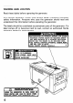
WARNING Read these LABEL LOCATION labels before operating the generator. Your Honda generator comes with several labels containing safety information. Anyoune who uses the generator should understand this information before operating the generator. important read and The labels should be considered as permanent parts of the generator. If a label comes off or becomes hard to read, contact an authorized Honda generator dealer for replacements. I ELECTROCUTION OR PROPERTY DAMAGE CAN OCCUR.
2. COMPONENT EXHAUST COOLING AIR OLJTLET / IDENTIFICATION OUTLET LIFTIYG HOOK , FUEL FILLER CAP TEST RECORD MAINTENANCE COVE MAINTENANCE COVER ENGINE OIL FILLER CAP PANEL OOLANT RESERVE TANK TTERY OIL LEVEL GAUG )OLANT DRAIN BOL ENGINE OIL DRAIN BOLT FRAME SERIAL NLkMBER I 68% \w FUEL DRAIN BOLT d ’ L FUEL FILTER * Record the frame serial number for your reference. Refer to the serial number when ordering parts, and when making technical or warranty inquiries (see page 46).
CIRCUIT PROTECTOR-2OA / CIRCUIT PROTECTOR-30A AC RECEPTACLE 30A 12OV INDICATOR LIGHTS AC RECEPTACLES 20A 120V I I / , ENGINE sv VITCH / : FUEL METER TACLE 50A AC I 1201I24OV I AC RECEPTACLk 30A 120124OV I CIRCUIT PROTECTOR-BOA 6 \ CIRdIT BREAKER \ CIRCUIT PROTECTOR-30A a \IUiR METER
3. CONTROLS Engine To start Switch and stop the engine. Key position: OFF: To stop the engine. ON: To run the engine START: To start the engine by turning the starter motor. Return the key to the ON position once the engine has started. Do not use the starter for more than 5 seconds at a time. If the engine fails to start, release the switch and wait 10 seconds before operating the starter again. Key can be removed/inserted. after starting.
Circuit Breaker The circuit breaker protects the individual circuit protectors and the 50A 120/24OV receptacle. The circuit breaker will automatically switch OFF if the circuit is overloaded or the appliance plugged into the circuit is faulty. If the circuit breaker is switched OFF automatically, check that the appliance is working properly or is exceeding the rated load capacity of the circuit before switching the circuit breaker ON again.
Ground m death Fault Circuit from Interrupter (GFCI) Receptacle Using the generator in rain, snow electric shock. Keep the generator This receptacle is protected protection against electrical by a Ground shock. or near water dry. Fault Circuit TEST BUTTON To test, depress the “TEST” (see pages 28, 29). RESET BUTTON To restore power, depress (see pages 28, 29).
Fuel Meter Indicates the amount of fuel in the fuel tank when the engine switch is in the ON position. Turn the engine switch to the OFF position and refill the fuel tank when the needle is near the “E” mark. FUEL METER I 71 Hour Meter Indicates the hours the gener,ator has been operated. Use it to determine when scheduled maintenance should be performed (see Page 33).
Indicator Lights The EB12D generator is equipped with four indicator lights that monitor three engine functions and the generator operation. All four lights come on when the engine switch is turned from the OFF position to the ON position. This allows the operator to check the bulbs of each indicator light. The for lights will stay on for 4 seconds with the engine switch left in the ON position. The lights will go out if the engine switch is turned to the start position before 4 seconds.
Generator Indicator Light The generator indicator light comes on and the engine Will stop automatically when there is a problem with the generator or the rated load capacity of the generator has been exceeded. If this occurs: l ,Turn the engine switch to the “OFF” position. l Disconnect the appliance from the generator. l Reset the AC circuit breaker or circuit protector.
4. PRE-OPERATION Check these items on a level surface. Maintenance Cover CHECKS before starting the generator. Be sure the generator is Block the wheels if the optional wheel kit is installed. Opening and Closing l To open: 1. Turn the maintenance cover opening knob to the OPEN position and pull up on the cover. 2. Pull the support from the holder and hook the end of the support as shown. l To close: 1. Lift the maintenance cover slightly to unhook the support from the hook. 2.
Engine Oil -1 En gine oil is a major factor affecting engine performance and service life. Running the engine with insufficient oil can cause serious engine damage. Non-detergent oil and 2-stroke engine oil are not recommended. Be sure to check the engine oil on a level surface with the engine stopped and the wheels blocked (if installed). Use only high-detergent premium quality motor oil certified to meet or exceed American Petroleum lnstitue (API) Service Classification CE, CD, or CDII.
Fuel Fuel tank capacity: 38 lit. (IO US gal, 8.4 Imp. gal1 Turn the engine switch ON and check the fuel meter. Refill the tank to the upper level if necessary. Do not fill the fuel tank above the upper level mark. Use ONLY clean high-quality fuel. Recommended fuel specifications: ASTM D-975-l -D/2-D Use No. 2-D fuel at temperatures above 20°F (-7OC) Use No. 1-D fuel at temperatures below 20°F (-7OC) Use No. 1 -D fuel for all temperatures at altitudes above 5000 ft (1500 m).
NOTE: l Depending on the season and the ambient temperature, a different grade of diesel fuel should be used. If a summer grade fuel is used in the winter, the summer fuel may freeze preventing the engine from starting. Winter grade fuel is used in the summer could result in a lack of engine power. Be sure to use the proper grade of diesel fuel which complies with the ambient temperature. l Keep the fuel tank filled in the winter.
Coolant 1. Open the maintenance cover (see page 13). 2. Check the coolant level in the reserve tank when the engine is at normal operating temperature. If the level is near the MIN level, add coolant to bring it up to the MAX level (see page 18 for coolant recommendation). MAX (UPPER LEVEL) I MIN (LOWER LEVEL) TANK 3. If there is no coolant in the reserve tank, the cooling system should be checked for leaks and repaired if necessary. Coolant must then be added to the radiator and reserve tank.
Coolant Recommendation Use high quality ethylene glycol antifreeze that is specifically formulated for use in aluminum engines. Mix the antifreeze with low-mineral drinking water or distilled water. A 50/50 mixture of ethylene glycol antifreeze and water is recommended for most temperature and provides good corrosion brotection. A higher concentration of antifreeze decrease cooling efficiency and is recommended only if additional protection against freezing is needed.
Battery The electrolyte level must be kept between the UPPER and LOWER level marks. If the electrolyte level is near the LOWER level, remove the battery filler caps and carefully add distilled water to the upper level line (see page 38). UPPER LEVEL LOWER LEVEL m The battery contains corrosive sulfuric or skin causes burns. Wear protective clothing when working near the battery. POISON-KEEP OUT OF REACH OF CHILDREN EMERGENCY Eyes acid.
Indicator lights Turn the engine switch to the ON position and check to see if the indicator lights come on. The indicator lights should go out after 4 seconds with the engine switch in the ON position. Return the engine switch to the OFF position. If the indicator light(s) does not come on, or do not go out after 4 seconds with the engine switch in the ON position, contact an authorized Honda generator dealer.
5. STARTING Starting Before AND STOPPING THE ENGINE the engine starting the engine 1. Open the maintenance the ON position. disconnect cover any load from the AC receptacle. (see page 13) and turn the fuel valve to ON 2. Close the maintenance cover (see page 13). 3. Turn the AC circuit breaker OFF.
4. Insert the key and turn the engine switch to the ON position. If the ambient temperature is below freezing, wait for the indicator lights to go OFF before turning the key to the start position. This allows the glows plug to pre-heat the combustion chambers. ON 5. Turn the engine engine starts. switch to the START /TiEiq position and hold it there until the Q) erating the starter motor for more than 5 seconds can damage the motor.
6. After the engine starts, let the engine switch return to the ON position. ON 7. Warm the engine for 2 or 3 minutes before applying a load to the generator. Blue smoke might be emitted from the exhaust during the warm-up. This is a normal occurrence. piEiq needed parts. pr oper engine warm-up will stabiliie the engine to warm-up the engine oil and properly lubricate speed.
Stopping the engine In an emergency: Turn the engine switch to the OFF position. -ENGINE In normal use: 1. Turn all electrical appliance’s connected 2. Turn the AC circuit breaker OFF. AC CIRCUIT 24 SWITCH BREAKER to the generator OFF.
3. Turn the engine switch to the OFF position. ENGINE 4. Open the maintenance the OFF position.
6. GENERATOR Connections 1 USE to a Building’s Electrical System If the generator will be used as an alternative to utility company power, an isolation switch must be installed to disconnect the utility lines from the building when the generator is connected. Installation must be performed by a qualified electrician and must comply with all applicable laws and electrical codes.
AC Applications Make sure all appliances are in good working order before connecting them to the generator. If an appliance begins to operate abnormally, becomes sluggish, or stops suddenly, turn it off immediately. Disconnect the appliance, and determine whether the problem is the appliance, or the rated load capacity of the generator has been exceeded. m Substantial overloading of the generator will switch off the circuit breaker.
Ground-Fault m death from Circuit Interrupter (GFCI) Receptacle Using the generator in rain, or snow or near water electric shock. Keep the generator dry. can lead to INSPECTION Before each use: If the generator is stored outdoors, unprotected GFCI receptacle before each use as described from the weather, test the in the monthly inspection. Monthly: Under normal operating conditions, perform the GFCI test Record your test on the GFCI test card provided on the control monthly. panel. 1.
-The RESET BUTTON should be flush with the test button. -If the RESET BUTTON is not flush with the TEST BUTTON, contact an authorized Honda generator dealer. 5. Press the RESET BUTTON i RESET BUTTON 6. When the RESET BUTTON extends during operation: l Unplug all appliance’s from the GFCI protected receptacle. l Press the RESET BUTTON. IF THE GFCI CAN NOT BE RESET: IF THE GFCI RESETS PROPERLY: The GFCI is faulty. Contact an authorized Honda generator dealer. Check the appliance or its cord.
Operation 1. Start the engine (see page 21). 2. Switch the AC circuit breaker ON. CIRCUIT BREAKER 3. Plug the appliance 30 into the appropriate AC receptacle.
How to use the receptacle When two or more receptacles are used, refer to the table below the load to each receptacle equally to prevent overloading. Voltage fluctuation can be prevented single phase receptacles. Receotacle I 240 \ by applying the load equally V 50 A LLCU v only 4 I. I H 30 A Iwax., 41.7 Using both 120 V and 240 V JU to the 120v 50 A 30 A 20 A Max. for both Case usmg and apply H Iwax. A Total Total 10 A Total 63.3 A Total 20 A Total 43.
7. MAINTENANCE Periodic maintenance and adjustment good operating condition. Service MAINTENANCE SCHEDULE. are necessary to keep the engine in and inspect according to the m To avoid carbon monoxide poisoning, shut off the engine before performing any maintenance. If you run the engine in an area that is confined, or even partially enclosed, the air you breathe could contain a dangerous amount of exhaust gas. If the engine must be run for any reason, be sure the area is well-ventilated.
Maintenance NOTE: Schedule (1) Service more frequently when used in dusty areas. (2) These items should be serviced by an authorized HONDA generator unless the owner has the proper tools and is mechanically proficient. Shop Manual. (3) For professional commercial use log hours of operation to determine maintenance intervals.
Engine oil change Drain the draining. oil while the engine is warm to assure complete and rapid 1. Open the maintenance cover (see page 13). 2. Remove the oil filler cap and drain plug to drain the oil. 3. After draining is complete, check that the sealing washer is in good condition (replace if necessary), then retighten the drain bolt securely. 4. Refill with the recommended engine oil and check the oil level with the oil level gauge (see page 14). 5. Install the oil filler cap. 6.
Air cleaner If you operate the generator in very dusty areas, check and replace the air cleaner more often than specified in the MAINTENANCE SCHEDULE. i m engine Operating wear. the engine , 1. Open the maintenance cover 2. Unhook the clips and remove AIR CLEANER COVER 3. Remove NOTE: dirty. the wing without ttie air cleaner will cause rapid (see page 13). the air cleaner cover and the inner cover. INNER COVER bolt and the air cleaner Do not clean the paper element. element.
4. Install the element, of removal. inner cover and air cleaner cover in the reverse order NOTE: Install the cover with the UP mark facing up and align the tabs of the inner cover and the air cleaner cover with the cutout of the air cleaner case. 5. Fasten the cover clips securely.
Fuel filter m condition. Diesel fuel is extremely Do not smoke or allow flammable and explosive under certain flames or sparks in the area. 1. Open the maintenance cover (see page 13). 2. Turn the fuel valve to the OFF position. 3. Loosen the ring nut and then remove the strainer cup, O-ring, spring and element. 4. Inspect the fuel in the strainer cup for contaminates or water. Clean the strainer cup thoroughly. 5. Install a new element using the spring, strainer cup, O-ring and ring nut.
Battery H Refilling battery fluid If the generator is operated with insufficient battery electrolyte, sulfation and battery plate damage will occur. If rapid loss of electrolyte is experienced, or if your battery seems to be your weak, causing slow starting or other electrical problems, see authorized Honda generator dealer. Open the maintenance cover and check the electrolyte level in each battery cell. Fill the battery with distilled water to the upper level line. Never overfill the battery.
n Battery cleaning If the battery terminals are contaminated and clean the terminals. or corroded, remove the battery Removal: ! 1. Remove the battery set plate. 2. Disconnect the negative (-1 battery cable first, then disconnect the positive (+) battery cable. 3. Remove the battery. 4. Clean the terminals with a wire brush or sand paper. Clean the battery with a solution of baking soda and warm water, taking care not to get the solution of water in the battery cells. Dry the battery thoroughly. 5.
Fuse replacement Turn the engine switch OFF and remove the key before checking ing fuses to prevent accidental short-circuiting. To replace a sub fuse, pull the old fuse out of the clips with Push a new fuse into the clips. If frequent fuse failure blem before attempting If a main fuse is blown, MAIN FUSE occurs, determine the cause to operate the generator. see an authorized Honda SUB FUSE your fingers. and correct generator the pro- dealer. 5A .
8. TRANSPORTING AND STORAGE The engine becomes very hot during operation and remains hot for a while after stopping. Allow the engine to cool before transporting or storing indoors. I Transporting i m burns + Contact with a hot engine or exhaust system can cause serious or fires. Let the engine cool before transporting or storing indoors. When transporting the generator, turn the engine switch to the OFF position and keep the generator level to prevent fuel spillage.
Before storing the generator for an extented period: 1. Be sure the storage area is free of excessive humidity and dust. 2. Clean the generator. 3. Check the generator according to the maintenance schedule (see page 33) and repair/replace any items as necessary. 4. Fill the fuel tank with fresh diesel fuel (see page 15). 5. Fully charge the battery. Recharge the battery once a month. 6. Cover the generator and place it in a well ventilated and dry area. Before starting the engine after storage: 1.
10. SPECIFICATIONS Dimensions EBI 2D Model Description Length ECD x Width x Height 139Ox630x815mm (54.7 x 24.8 x 32.1 Dry weight 340 kg (701 in) lb) Engine Model GDI 100 Type I 4 -stroke Displacement [Bore x Stroke1 Rated Max. OHC 3 cylinder 20 PS/3,600 torque 55.9 system Combustion diesel min-1 (rpm) N.m (5.7 kg-m, 41.2 2,000 min-1 (rpm) Liquid method Direct Fuel capacity ft-lb)/ cooled injection Diesel Fuel tank cooled 1061 cm3 [76 x 78 mm (3.0 x 3.
___ ..I --.
12. WARRANTY SERVICE Owner Satisfaction Your satisfaction and goodwill are important to your dealer and to us. All Honda warranty details are explained in the Distributor’s Limited Warranty. Normally, any problems concerning the product will be handled by your dealer’s service department. If you have a warranty problem that has not been handled to your satifsaction, we suggest you take the following action: l l Discuss your problem with a member of dealership management.
MEMO 47
I MEMO 48