Thank you for purchasing a Honda tiller. This manual covers operation and maintenance of FR500 and FR700 tillers. All information in this publication is based on the latest product information available at the time of approval for printing. The illustrations in this manual are based on the FR500 tiller. Honda Motor Co., Ltd. reserves the right to make changes without notice and without incurring any obligation. at any time No part of this publication permission.
CONTENTS 1. 2. 3. 4. 5. 6. 7. 8. 9. 10. 1 1. 2 SAFETY INFORMATION ....................................................... ............................................. COMPONENT IDENTIFICATION PRE-OPERATION CHECK ...................................................... STARTING THE ENGINE ....................................................... TILLER OPERATION ............................................................. STOPPING THE ENGINE .......................................................
1. SAFETY Read all safety instructions INFORMATION before operating.
To ensure safe operation- For your safety precautions: Operator and the safety of others, pay special attention to these Responsibility Keep the tiller in good operating condition. Operating a tiller in poor or questionable condition could result in serious injury. Be sure all safety devices are in working order and warning labels are in place. These items are installed for your safety. Be sure the safety covers (V-belt cover, chain cover and recoil starter cover) are in place.
Child Safety l l l Keep children indoors and supervised at all times when any outdoor power equipment is being used nearby. Young children move quickly and are attracted especially to the tiller and the tilling activity. Never assume children will remain where you last saw them. Be alert and turn the tiller off if children enter the area. Children should never be allowed to operate the tiller, even under adult supervision.
Fire and Burn Hazard Gasoline is extremely flammable, and gasoline vapor can explode. Use extreme care when handling gasoline. Keep gasoline out of reach of children. l Refuel in a well-ventilated area with the engine stopped. l Allow the engine to cool before refueling. Fuel vapor or spilled fuel may ignite. l The engine and exhaust system become very hot during operation and remain hot for a while after stopping. Contact with hot engine components can cause burn injuries and can ignite some materials.
2. COMPONENT IDENTIFICATION IGNITION SWITCH / MUFFLER FUEL TANK CAP \ FUEL TANK \ / CLUTCH - LEVER - SHIFT LEVER ROTARYCLUTCH LEVER V-BELT COVER DRAG BAR ROTAfiY TINES THROTTLE LEVER SIDE-COVER HEIGHT ADJUSTER \ AIR CLEANER P lFRAMF ROTARY TINES / WHEEL WEIGHT RECOIL’STARTER * Record the frame and engine serial numbers for your reference. Refer to the serial numbers when ordering parts, and when making technical or warranty inquiries (see page 38).
3. PRE-OPERATION ENGINE CHECK OIL 1 IMPORTANT NoT’CE 1 Running serious engine damage. the engine with low oil level will cause a. b. c. d. Place the tiller on a level surface. Remove the oil filler cap and wipe the dipstick clean. Insert the dipstick into the oil filler neck, but do not screw it in. Check the oil level shown on the dipstick. If near the lower level, fill to the upper level with the recommended oil.
Transmission oil With the tiller on level ground, remove the oil filler cap and to see check if oil is up to the tip of the dipstick. Add engine oil if necessary (see page 8 for recommended oil). OIL FILLER CAP Air cleaner Remove the cover and inspect the elements; clean them if necessary (see page 28). With the tiller in a level position, check the case oil level. If necessary, add oil to the mark on the case see page 8 for recommended oil.
Rotary oil level Place the tiller on level ground and remove the oil level check bolt. The oil level should be up to the lower edge of the check bolt hole. If the level is low, add engine oil until it begins to flow out of the hole (see page 8 for recommended oil).
FUEL Remove the gas cap and check the fuel ‘level. Refill the tank if the level is low. Fuel tank capacity: FR500: FR700: 2.7 e (0.74 US. gal) 3.7 e (1 .O US. gal) Gasoline is extremely flammable, and gasoline vapor can explode. Use extreme care when handling gasoline. Keep gasoline out of the reach of children. Refuel in a well ventilated area with the engine stopped. Keep flames and sparks away, and do not smoke in the area. Gasoline vapors or spilled gasoline may ignite.
Gasoline Recommendation Pump octane rating: 86 or higher We recommend unleaded gasoline because it produces fewer engine and spark plug deposits and extends the exhaust system life. If “spark knock” (metallic rapping noise) or persistent “pinging” occurs at a steady engine speed under normal load, change brands of gasoline. If spark knock or pinging persists, see an authorized Honda tiller dealer. 1 IMPORTANT pinging NOTICE 1 R unning can cause engine the engine damage.
GASOLINES CONTAINING ALCOHOL If you decide to us‘e a gasoline containing alcohol (gasohol), be sure its octane rating is at least as high as that recommended by Honda (see Gasoline Recommendation on page 12). There are two types of “gasohol”: one containing ethanol, and the other containing methanol. Never use gasoline containing more than cosolvents and corrosion inhibitors.
4. l l STARTING THE ENGINE Exhaust contains poisonous carbon monoxide gas; exposure can cause loss of consciousness and may lead to death. Never run the engine in an enclosed or confined area. The muffler becomes very hot during operation and remains hot for a while after stopping the engine. Be careful not to touch the muffler while it is hot. FUEL VALVE 1. Turn the fuel valve ON. 2. Turn the ignition switch to ON. IGNI SWI 3.
4. Move the throttle lever about 30 degrees from the extreme right (idle position). THROTTLE LEVER NOTE: The clutch is engaged by pulling in the clutch lever and disengaged by releasing the lever. DlSENGiGED 5. Make sure the clutch is disengaged and the transmission is in neutral; then pull the starter rope briskly to start the engine. IMPORTANT NOTICE Do not allow the starter grip to snap back against the engine. Return it gently to prevent damage to the starter.
6. Let the engine warm up for several minutes. If the choke has been pulled out to the CLOSE position, return it gradually to the OPEN position as the engine warms up. 7. Move the throttle lever to the left as desired to increase engine speed.
l FR700 models with electric starter 1. Turn the fuel valve to the ON. 2. In cold weather and when the engine is cold, pull the choke knob to the CLOSE position. NOTE: Do not use the choke if the engine is warm or the air temperature is high. a CHOKE KNOB 3. Move the throttle lever about 30 degrees from the extreme right (idle position).
4. Turn the engine switch to START and hold it there until the engine starts. NOTE: The battery will automatically recharge while the tiller is operated. If the tiller is not operated frequently enough to keep the battery charged, there will be a decrease in starter motor speed. If the battery is too dischaged to run the starter motor, use the recoil starter. ENGINE SWITCH 5. After the engine starts, let the engine switch return to ON. ENGINE SWITCH 6. Let the engine warm up for several minutes.
7. Move the throttle lever to the left as desired to increase engine speed.
5. TILLER OPERATION BEFORE ADJUSTING 1. Handlebar 1 IMPORTANT firm, height THE HANDLEBAR, BE SURE THE ENGINE adjustment NOTICE 1 B e f ore adjusting level ground to prevent the handle the handlebar, place the tiller from collapsing accidentally. To adjust the handlebar height, loosen the adjuster knob, select the appropriate holes in the handle column and handlebar bracket, and tighten the knob. 2.
4. Rotary Clutch Operation/Tilling SHIFT LEVER To work the tiller 1. Start the engine. 2. With the throttle at idle and the clutch disengaged, select a forward gear. 3. Return the throttle to the engine start position (about 30° from idle), and engage the clutch. 4. Move the rotary clutch forward (position 1) and the tines will turn. 5. Increase engine speed as necessary. SITION ROTARi LEVER CLUTCH To stop the tiller 1. Move the rotary clutch to (position 2) and stop the engine. 5.
6. Wheel Weight Installation The wheel weights improve traction on soft or marshy ground. To install the weights, insert two bolts and secure them with the nuts supplied. Tighten the bolts and nuts securely to prevent them from loosening during operation. 7. Tire Pressure Excessive tire pressure will reduce traction, and underinflation may result in abnormal or accelerated tire wear. For best performance, keep the tires inflated to 1.2 kg/cm’ (17.1 psi).
8. Rotary Wear tine inspection/replacement heavy gloves to protect your hands. Check for worn, bent or other damaged of the rotary tines. Check for damage dor loose bolts and nuts. Tighten and/or replace them if necessary. IMPORTANT Rotary NOTICE 1 Use only a genuine HONDA replacement tine A and rotary tine B are not interchangeable. Bolt and nut directions 10 mm BOLTS A rotary tine.
6. STOPPING THE ENGINE 1. Move the throttle to the idle position (Extreme right). 2. Release the clutch lever and move the shift lever to the “N” (Neutral) position. 3. Turn the ignition stop engine. switch OFF to Recoilstartertype OFF , Electric starter type OFF 4. Turn the fuel valve OFF. NOTE: To stop the engine in an emergency, release the clutch lever and turn the igniton switch OFF. .
High Altitude Operation At high altitude, the standard carburetor air-fuel mixture will be too rich. Performance will decrease, and fuel consumption will increase. A very rich fuel mixture may also foul the spark plugs and cause hard starting. High altitude performance can be improved by installing a smaller diameter main fuel jet in the carburetor and readjusting the pilot screw.
7. MAINTENANCE The purpose of the maintenance schedule is to keep the tiller in the best operating condition. Inspect or service as scheduled in the table below. m Shut off the engine before performing any maintenance. Exhaust contains poisonous carbon monoxide gas; Exposurs can cause loss of consciousness and may lead to death. If the engine must be run, make sure the area is well ventilated.
1. Engine oil change NOTE: Change the oil when the engine is warm to assure rapid and complete draining. 1. Remove the oil drain bolt and the filler cap. 2. Tilt the engine forward slightly and allow all of the oil to drain. 3. Reinstall and tighten the oil drain bolt and fill engine with oil to the upper oil level (See page 8 for recommended oil). 4. Reinstall and tighten the filler cap. OIL CAPACITY: FR500-0.7 FR700-1.2 e (0.74 US qt) P (1.
2. Air cleaner service A dirty air cleaner will restrict air flow to the carburetor. To prevent carburetor malfunction, service the air cleaner regularly. Service more frequently when operating the engine in extremely dusty areas. m air cleaner Never use gasoline or low flash point solvents element. A fire or explosion could result. 1 IMPORTANT NoT’CE 1 Never engine wear will result. run the engine 1. Remove the air cleaner cover.
3. Clean sediment cup Turn the fuel valve to the off position and remove the sediment cup and Oring. Wash removed parts in solvent, dry them thoroughly and reinstall them securely. Turn the fuel valve ON and check for leaks. SEDIMENT CUP (FR500 only) 4. Transmission oil change NOTE: Change the oil when the engine is warm to assure rapid and complete draining. 1. Remove the oil filler cap and drain bolt, and allow the oil to drain. 2.
5. Rotary oil level Place the tiller on level ground and remove the oil level check bolt. Remove the oil filler cap. The oil level should be up to the lower edge of the check bolt hole. 3. If the level is low, add oil until it begins to flow out of the hole (See page 8 for recommended oil). :: OIL CAPACITY: 0.35 (0.38 US qt) 4. Tighten the check bolt securely. 5. Install the oil filler cap. OIL CHECK BOLT OIL FILLER CAP 6. Spark plug service.
3. Visually inspect the spark plug. Discard it if the insulator is cracked or chipped. Clean the spark plug with a wire brush if it is to be reused. 4. Measure the plug gap with a feeler gauge. The gap should be 0.6-0.7 mm (0.024-0.028 in). Correct as necessary be bending the side electrode. 0.6-0.7 5. Attach the plug washer. threading. mm (0.024-0.026 in) Thread the plug in by hand to prevent cross- 6. Tighten a new spark plug l/2 after the plug seats turn with the wrench to compress the washer.
7. Throttle cable adjustment Loosen the lock nut and turn the throttle cable adjusting nut until free play at the throttle lever is between 5- 10 mm (I /4- 3/8 in) as shown. Tighten the lock nut securely. LOCK NUT THROTTLE CABLE LOCK NUT EE PLAY 8. Clutch Cable Adjustment 1. Remove the V-belt cover. 2. Loosen clutch cable the lock nut and turn the adjusting nut so that distance (A) is within the following limits, when the clutch is disengaged. CLUTCH C.
9. V-belt Adjustment 1. Remove the cover. 2. Engage the clutch and measure distance (A), it should be within the limits shown. To adjust, loosen five engine mounting bolts and shift the engine forward to tighten the belts. Tighten the bolts securely. 3. Measure clearances (B) and (C) to see if they fall within the following specifications: (B) 3-5 mm (0.12-0.20 in) (C) 6-8 mm (0.24-0.32 in) To adjust, loosen the belt stopper tightening bolts and slide the stoppers as required. 4.
10. Upper chain adjustment 1. Remove the primary chain case cover. 2. Check chain slack midway between the sprockets; it should be 20-30 mm (0.791 .I 8 in). To adjust tension, loosen the tensioner adjusting bolts and move the tensioner up or down as necessary. 6 mm ADJUST BOLTS 11. Fuse replacement (FR700 with electric starter) If the fuse has blown, If the fuse is changed again. replace it with a 5A fuse after checking the cause.
13. Battery Service Recharge the battery time. if the tiller is to be stored for an extended period of During the storage, the battery should also be recharged every 6 months. To recharge the battery, use a commercially available battery charger whose max. Charging current is rated below 3 A. The tiller is equipped a maintenance-free battery which does not require checking and refilling of the battery fluid. Under no circumstances should the caps be removed from the battery cells. 1.
l l The battery gives off explosive gases; keep sparks, flames and cigarettes away. Provide adequate ventilation when charging or using the batteries in an enclosed space. The battery contains sulfuric acid (electrolyte). Contact with skin or eyes may cause severe burns. Wear protective clothing and a face shield. - If electrolyte gets on your skin, flush with water. - If electrolyte gets in your eyes, flush with water for at least 5 minutes and call a physician immediately.
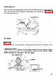
8. TRANSPORTING/-STORAGE m When transporting the tiller, turn the fuel valve OFF and keep the tiller level to prevent fuel spillage. Fuel vapor or spilled fuel may ignite. Before storing the unit for an extended period; 1. Be sure the storage area is free of excessive humidity and dust. 2. Drain the fuel . . . a. With the fuel valve turned OFF, remove and empty the sediment cup. b. Turn the fuel valve ON and drain the gasoline in the fuel tank into a suitable container. c.
9. TROUBLESHOOTING When the engine will not start; 1. Is there enough fuel? 2. Is the fuel valve ON? 3. Is the engine switch ON? 4. Is gasoline reaching the carburetor? To check, loosen the drain screw with the fuel valve on. Fuel should flow out freely. Retighten drain screw. m If any fuel is spilled, make sure the area is dry before testing the spark plug or starting the engine. Fuel vapor or spilled fuel may ignite. A DRAIN SCREW 5. Is there a spark at the spark plug? a. Remove the spark plug cap.
IO. FR500 Model Dimensions (L x W x HI FR700 A: 1,510 (59.4 AS: 1,595 (62.7 1,340 x 620 x 960 mm (52.8 x 24.4 x 37.8 in) 100 kg (220.5 lb) Dry weight x 620 x 24.4 x 620 x 24.4 x x x x 980 38.4 980 38.4 mm in), mm in) A: 115 kg (253.6 lb), AS: 121 kg (266.8 lb) 350-7 Tire size Maximum handle height Engine Model 1,230 mm (48.4 in) 1,290 mm (50.
11. Owner WARRANTY SERVICE Satisfaction Your satisfaction and goodwill are important to your dealer and to us. All Honda warranty details are explained in the Distributor’s Limited Warranty. Normally, any problems concerning the product will be handled by your dealer’s service department. If you have a warranty problem that has not been handled to your satisfaction, we suggest you take the following action: l Discuss your problem with a member of dealership management.