Thank you for purchasing This manual snowblower. covers the a Honda snowblower. operation and maintenance of the All information in this publication is based on the latest product tion available at the time of approval for printing. HS828 informa- Honda Motor Co., Ltd. reserves the right to make changes without notice and without incurring any obligation. at any time No part of this publication permission.
CONTENTS SAFETY ........................................................................... COMPONENT IDENTIFICATION ........................................... CONTROLS ...................................................................... PRE-OPERATION CHECK .................................................... STARTING THE ENGINE ..................................................... 65: SNOWBLOWER OPERATION ............................................... 7. STOPPING THE ENGINE ............................
1. SAFETY SAFETY LABEL LOCATIONS Read these labels before operating the snowblower.
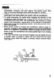
To ensure safe operation l Always make a pre-operation check (pages 16 thru 20) before you start the engine. You may prevent an accident or equipment damage. l Honda snowblowers are designed to give safe and dependable service if operated according to instructions. Read and understand this Owner’s Manual before operating the snowblower. Failure to do so could result in personal injury or equipment damage. l Before operating the snowblower, inspect the area in which you are going to clear snow.
Adjust the snow discharge chute to avoid hitting the operator, bystanderds, windows, and other objects with ejected snow. Stay clear of the snow discharge chute while the engine is running. Children and pets must be kept away from the area of operation to avoid injury from flying debris and contact with the snowblower. To avoid overturning, be ‘careful when changing the direction of the snowblower while operating it on a slope. Do not use the snowblower to remove snow from roofs.
l l l Gasoline is extremely flammable and is explosive under certain conditions. Do not smoke or allow flames or sparks where the snowblower is refueled or where gasoline is stored. Refuel in a well-ventilated area with the engine stopped. Do not overfill the fuel tank, and make sure the filler cap is closed securely after refueling. Never run the engine in an enclosed or confined area. Exhaust contains poisonous carbon monoxide gas; exposure can cause loss of consciousness and may lead to death.
2. COMPONENT IDENTIFICATION Al JGER CLUTCH LEVER CHUTE GUIDE ILE” c\,cm \ C” \ DRIVE CLUTCH /LEVER I SNOW DISCHARGE CHUTE ‘SHIFT \ LEVER THROTTLE LEVER AUGER ,AC STARTER BUTTON CAP ENGINE SWITCH 4 TRANSMISSION FLUID RESERVOIR FUEL VALVE CHUTE CR FOOT PEDAL -\ FRAME SERIAL NUM SKID PLATE \ TRANSMiSSlON RELEASE LEVER \ ENGINE SERIAL NUMBER Record the frame and engine serial numbers for your reference.
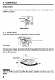
3. CONTROLS Engine switch Use the engine switch STOP the engine. to turn the ignition system ON for starting, and to ---+/I STOP (OFF) (ON) ENGINE StilTCH A. C. starter button Push the starter button to operate the electric starter. STARTER BUTTON Fuel valve The fuel valve opens and closes the fuel line leading from the fuel tank to the carburetor. Make sure that the valve is positioned exactly at either the ON or OFF position.
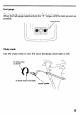
Fuel gauge The fuel gauge indicates the amount of fuel in tlie tank. When the fuel gauge needle enters the “E” renge, refill the tank as soon as possible. FUEL GAUGE Chute crank Use the chute crank to turn the snow discharge chute right or left.
Starter grip Pull this grip to start the’ engine. STARTER GRIP Throttle lever (Engine speed) The throttle lever controls engine speed from SLOW to FAST; it will stay in any designated position. Set the lever to CHOKE when the engine is cold.
Shift lever The shift lever selects hydrostatic transmission FORWARD drive. (F), NEUTRAL (N), or REVERSE (RI The shift lever also controls the transmission drive ratio; moving the lever farther from NEUTRAL increases drive speed. While clearing snow, use the shift lever to control drive speed, so you can leave the throttle lever in the FAST position for best snow-clearing performance. REVERSE SHIFT LhER Chute guide The chute guide controls the snow discharge angle.
Drive clutch lever and auger clutch Use these controls drive mechanism. lever to engage the snow blowing mechanism / and/or the DRIVE CLUTCH LEVER Squeeze to engage the drive machanism. AUGER CLUTCH LEVER Squeeze to engage the snow blowing mechanism. NOTE: When both levers are squeezed, the drive clutch lever locks the auger clutch lever down. Releasing the drive clutch lever then unlocks and releases the auger clutch lever.
Skid plate, Scraper Adjust the skid plates for the auger ground clearance snow removal conditions. best suited to your m To prevent accidental starting, turn the engine OFF position and disconnect the spark plug cap. switch to the 1. Place the snowblower on a level surface and set the height adjustment pedal in the middle position. 2. Move the skid plates up or down to obtain the desired auger ground clearance. 4-8 mm (0.16-0.31 in) For ordinary snow: O-5 mm (O-0.
Foot pedal Use the pedal for adjusting to the tracks. 1. Hold the handles 2. Raise or lower pedal. the height and angle of the machine in relation and step on the pedal. the machine to the desired : Hand snow or fine finish LOW MIDDLE: Normal use : Deep snow or for transporting HIGH position and release the the snowblower.
Transmission release lever The transmission release lever has two positions, RELEASED and ENGAGED. Set the lever in the ENGAGED position when throwing snow; set it in the RELEASED position when pushing the snowblower. m throwing accident. Never shift the transmission release lever on slopes. The snow mechanism may operate suddenly, causing serious injury or riziEq (-Jperating the transmission ning can damage the transmission. release lever while the engine is run- 1. Stop the engine. 2.
4. PRE-OPERATION Check the snowblower CHECK on level ground with the engine stopped. m To prevent accidental start-up, remove the engine switch key, and disconnect the spark plug cap before performing the pre-operation inspection. Fuel Check the fuel gauge, and refill the tank if the fuel level is low. Refuel carefully to avoid overfilling or spilling fuel. There should be no fuel in the filler neck. FUEL TANK m plode. CAPACITY: Gasoline Use extreme 6.0 P (1.
Fuel Recommendation Use gasoline with a pump octane rating of 86 or higher. We recommend unleaded fuel because it produces fewer engine and spark plug deposits and extends exhaust system life. Never use stale or contaminated gasoline or an oil/gasoline mixture. Avoid getting dirt or water in the fuel tank. Occasionally you may hear light “spark knock” or “pinging” (metallic rapping noise) while operating under heavy loads. This is no cause for concern.
Engine oil Inspection: With the snowthrower on a level surface, remove the oil filler cap and wipe the dipstick clean. Insert the dipstick into the filler neck, but do not screw it in. Remove the dipstick and check the oil level. If the level is low, fill to the top of the oil filler neck with the recommended oil. -20 -30 0 -20 20 -10 40 0 EO’F 1ooc UPPER -LEVEL OIL FILLER CAP AND DIPSTICK OIL CAPACITY: RECOMMENDED 1.1 P (1.
HYDROSTATIC TRANSMISSION FLUID Check the hydrostatic fluid level in the reservoir. Hydrostatic fluid expands and contracts with changes in temperature. The UPPER and LOWER level marks on the reservoir are calibrated for room temperature fluid. It is normal for the fluid level to rise above the UPPER level mark when snowblower operation warms the transmission. When checking the level of cold fluid, below room temperature, refer to the temperature chart for appropriate fluid levels.
Auger and blower bolts Check the auger and blower for loose or broken bolts. If broken, them with new ones (page 39). replace BLOWER SHEAR BOLT AUGER SHEAR BOLT Other checks 1. Check all bolts, nuts and other fasteners for security. 2. Check each part for operation. 3. Check the entire machine for any other faults which might have been caused in previous operation.
5. STARTING THE ENGINE m Never run the engine in an enclosed or confined area. Exhaust cdntains poisonous carbon monoxide gas; exposure can cause loss of consciousness and may lead to death. 1. Move the shift lever to “N” (Neutral). “N” (Neutral) SHIFT LEVER 2. Turn the fuel valve to the ON position. FUEL VALVE .
3. Set the transmission release lever in the ENGAGED position. ENGAGED TRANSMISSION RELEASE LEVER 4. In cold weather and when the engine is cold, move the throttle CHOKE position.
5. Connect your power cord to the switch box and the male end of the power cord to a properly grounded 120 Volt A/C outlet. ACAUTI~N WUSE ONLY WITH GROUNOEO OUTLET AN0 3-WIRE CORD. I120 VOLT A.C. ONLY IO0 NOT CRANK OVER 1 MINUTE WITHOUT COOLING 15 MINUTES. IO0 NOT USE IN RAIN. -0,:. l l l CORD To minimize the possibility of potentially dangerous electrical shocks, always use a 3-conductor power cord with a power rating of no less than 15 amps.
7. Push the starter button until the engine starts. After the engine starts, disconnect the power cord from the electrical outlet first, and then from the switch box. PUSH 1-1 Do not operate the starter for more than 1 minute. If the engine fails to start, release the button and allow the starter to cool for 15 minutes before operating it again. [MANUAL STARTING 8. Pull the starter ONLY] grip lightly until you feel resistance then pull briskly.
9. After starting the engine, allow it to run for a few seconds to warm it up to operating temperature. As the engine stabilizes, gradually move the throttle lever to the SLOW position. SLOW THROTTLE LEVER 10. While warming the engine up, also warm the transmission (1) Check that the shift lever is in the “N” (Neutral) as follows: position. “N” (Neutral) SHIFT LEVER (2) Squeeze the drive clutch lever for about 30 seconds.
6. SNOWBLOWER OPERATION m Before operating this equipment you should read and understand the SAFETY INFORMATION on page 3, 4, 5 and 6. 1. Start the engine according to the procedures described on page 21. 2. Move the throttle lever to the FAST position for normal operation. 3. Release the auger clutch lever, and move the shift lever to select the desired drive speed. REVERSE “N” (Neutral) SHIFT LEVER NOTE: Low speed is recommended snow. for removing deep or hard-packed 4.
6. Squeeze the auger clutch lever. The machine will clear snow when you squeeze the auger clutch lever. AUGER CLUTCH LEVER 7. Squeeze the drive clutch lever. If the transmission release lever (p. 22) is in the ENGAGED position, and the shift lever (p. 26) is in the FORWARD (F) position, the hydrostatic drive will propel the snowblower forward when you squeeze the drive clutch lever. DRIVE CLUTCH LEVER / When both levers are squeezed, the drive clutch lever locks the auger clutch lever down.
To move from one place to another, or to change direction, use the drive clutch lever only. Release both the drive clutch lever and auger clutch lever once, then squeeze the drive clutch lever. DRIVE CLUTCH LEVER / 8. Release the clutch levers to stop clearing and moving.
Clearing Snow For best efficiency, clear snow before it melts, refreezes and hardens. not reduce engine speed while clearing snow. Do Operating tips for clearing hard or deep snow: l Reduce forward speed. If that is not sufficient, use the shift lever to clear snow with a back and forth motion. l Clear a narrower swath. Make several passes with the auger overlapping the cleared areas. l If the snow is deeper than the height of the auger, remove it in several steps, as shown below.
l l l Adjust the snow discharge chute to avoid hitting the operator, bystanders, windows, and other objects with thrown snow. Stay clear of the snow discharge chute while the engine is running. If the snow discharge chute becomes clogged, stop the engine and use a wooden stick to unclog it. Never put your hand into the snow discharge chute while the engine is running; serious personal injury could result. To move from one place to another, or to change direction, use the drive clutch lever.
7. STOPPING To STOP the immediately. engine in an emergency, turn the THE ENGINE engine switch OFF STOP (OFF) \ To restart position. the engine, move the shift lever back to the “N” 1. Release the auger and drive clutch levers. The machine and snow throwing mechanism (Neutral) will stop operation. AUGER CLUTCH LEtiER DRIVE CLUTCH LEVER 2. Move the ,shift lever to “N” (Neutral) position.
3. Turn the throttle lever to the SLOW position. SLOW THROTTLE LEVER 4. Turn the engine switch to the OFF position. STOP (OFF) E S 5. Turn the fuel valve to the OFF position. FUEL VALVE b!%%l If th e snowblower is parked on a slope, leave the transmission release lever in the ENGAGED position to prevent the machine from rolling downhill.
8. MAINTENANCE Periodic inspection and maintenance will help extend the service life of your HS828 Snowblower while keeping it in the best operating condition. Inspect or service as described on the next page. l l I Shut off the engine before performing inspection and maintenance, and disconnect the spark plug wire from the plug so that the engine cannot be started. If the engine must run, make sure the area is well ventilated.
Maintenance NOTE: schedule (1) These parts may (2) These items should proficient. See Shop the Honda more frequent be serviced is mechanically (31 For professional 34 require inspection by an authorized and replacement Honda dealer. unless under heavy the owner use. has the proper tools Manual. commercial use. log hours of operation to determine proper maintenance intervals.
TOOL KIT IN 0 SPARK PLUG WRENCH r BLOWER SHEAR BOLT I WRENCH HANDLE 10 x 14 mm WRENCH D-J 6 mm SELF LOCK NUT AUGER SHEAR BOLT (3) 6 mm HEX NUT (3) 12 x 14 mm WRENCH TOOL BAG 35
Engine oil change Drain the oil while the engine is still warm to assure rapid and complete draining. 1. Place the snowblower on a level surface. Before you drain the oil, set the snowblower in the HIGH position by operating the foot pedal (see page 14). 2. Remove the drain plug and filler cap, and drain the oil. Retighten the plug securely. 3. Fill the crankcase with the recommended oil (see page 18) and check the level. OIL CAPACITY: 1.1 P (1.
Spark plug service Recommended m careful spark plug: BPR5ES (NGK), Wl GEPR-U (NIPPONDENSO) If the engine has been running, the muffler not to touch the muffler while it is hot. will be very hot. Be To ensure proper engine operation, the spark plug must be properly gapped and free of deposits. 1. Remove the spark plug cap. 2. Clean any dirt from around the spark plug base. 3. Use the wrench supplied in the tool kit to remove the spark plug. 4. Inspect the spark plug.
Track-Adjustment Make sure the tracks are clean and dry before adjustment. The tracks cannot be correctly adjusted if clogged with snow or debris, or coated with ice. Check track deflection by pressing down midway between the wheels. When correctly adjusted, the track will deflect 27-33 mm (1.061.30 in) when pressed with a force of 15 kg (33 lb). 27-33 (1.06- mm 1.30 in) TRACk ADJUSTING PROCEDURE: 1.
Auger/Blower inspection Check the auger, auger housing, blower and shear bolts for signs of damage or other faults. If any of the shear bolts are broken, replace them with the one furnished with the snowblower. Additional shear bolts and nuts are available from authorized Honda snowblower dealers. -1 Sh ear bolts are designed to break under force that would otherwise damage auger and blower parts. Do not replace shear bolts with ordinary hardware bolts. Shear bolt replacement 1. 2. 3. 4. 5.
9. TRANSPORTING Before loading 1. Loading the snowblower on a trailer should be performed on a firm, level surface. 2. Use a loading ramp that is strong enough to support the combined weight of the snowblower and the operator: Weight of snowblower: 116 kg (253.4 lb) (Operating weight) 3. The loading ramp must be long enough so that its slope is 15O or less: Length of Ramp (PI --l-T h ’ ‘-‘lht (h) 1 2.5 m (8.2 ft) ( 3.0 m (9.8 ft) 50 cm (1.6 ft) 60 cm (2.0 ft) 1 3.5 m 1 (1 1.5 ft) 70 cm (2.
3. Run the snowblower slowly up the loading ramp. Be careful to avoid striking the chute or other parts of the machine. FORWARD 1.5 m (4.9 ft) minimum headroom 4. After the snowblower is in the truck, stop the engine, and turn the fuel valve to the OFF position. This will prevent the possibility of carburetor flooding and will reduce the possibility of fuel leakage. 5. Tie the snowblower down with rope or straps, and block the treads. Keep the tie-down rope or straps away from controls and cables.
10. STORAGE Before storing the snowblower for an extended 1. Be sure the storage area is free of excessive 2. Drain the fuel. period: humidity and dust. m Gasoline is extremely flammable and explosive under certain conditions. Do not smoke or allow flames or sparki in the area. Do not drain the fuel tank when the exhaust system is hot. a. Turn the fuel valve ON. b. Loosen the carburetor drain screw, and drain the gasoline into a suitable container.
4. Remove the spark plug and pour a tablespoonsftil of clean motor oil into the cylinder. Pull the starter rope slowly two or three times to distribute the oil. Reinstall the spark plug. 5. Pull the starter grip until resistance is felt. This closes the valves and protects the,engine from internal corrosion.
6. Apply oil to the following CHUTE SLIDING SURFACE AUGER AND BLOWER 44 parts for lubrication and rust prevention.
11. TROUBLESHOOTING When the engine will not start: 1. Is there enough fuel! 2. Is the fuel valve on? 3. Is gasoline reaching the carburetor? To check, loosen the drain screw with the fuel valve on. Fuel should flow freely. m Gasoline is extremely flammable, and gasoline vapor can explode. If any fuel is spilled, make sure the area is dry before testing the spark plug or starting the engine. 4. Is the engine switch on? 5. Is there a spark at the spark plug? a. Remove the spark plug cap.
12. SPECIFICATIONS Engine HONDA Model Maximum output GX 240 8 HP/3,600 rpm Displacement 242 Bore x stroke 73 x 58 mm (2.9 Starting Recoil starter method Ignition cm3 (14.8 cu in) Transistorized system 1.1 P (1.16 Oil caoacitv Fuel tank capacity 1 6.0 Spark 1 BPR5ES plug P (1.59 x 2.3 in) or AC electric starter magneto US qt.) US gal.
13. WARRANTY Owner SERVICE Satisfaction Your satisfaction and goodwill are important to your dealer and to us. All Honda warranty details are explained in the Distributor’s Limited Warranty. Normally, any problems concerning the product will be handled by your dealer’s service department. If you have a warranty problem that has not been handled to your satisfaction, we suggest you take the following action: l Discuss your problem with a member of dealership management.