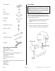
www.collegehillshonda.com/parts Accessory INSTALLATION INSTRUCTIONS PARTS LIST Security System (sold separately): P/N 08E51-S01-101F Application Publications No.
3-Pin connector INSTALLATION Customer Information: The information in this installation instruction is intended for use only by skilled technicians who have the proper tools, equipment, and training to correctly and safely add equipment to your car. These procedures should not be attempted by “do-it-yourselfers.” Nut Washer NOTE: The Owner’s Manual included with the Security Attachment should be placed in the glove box for future reference.
4. Remove the driver's dashboard lower cover: • • Remove the three screws. Gently pull along the top to release the three retaining clips. • Unplug the connector(s) and remove the cover. 6. Remove the left kick panel (two clips, and slide back while pulling its lower end inside). RETAINING CLIP CLIP (LARGE) CLIP LOWER END LEFT KICK PANEL 7. SELF-TAPPING SCREW Remove the upper steering column cover (three screws and six clips).
Intalling the LED 8. 9. 11. Carefully push the LED terminals into the 2-pin connector from the kit. Measure and mark the upper steering column cover removed in step 7, and lightly center-punch the mark. LOCK Insert the tabs into the grooves, slide the lock toward the front, and press down on the end. Insert. While wearing eye protection, drill a 5.5 mm hole through the center-punched mark. Remove all burrs. 5.
13. Route the terminal ends of the disarm switch harness through the 12 mm hole you just drilled in the dashboard lower cover. Secure the disarm switch on the dashboard lower cover using the 12 mm and washer provided. Tighten the nut securely. Installing the Control Unit 16. Loosen the bolt on the right of the steering shaft, then slide the slot of the control bracket under the head of the bolt you just loosened.
18. Position the control unit on the control bracket, and install the two collars and two 4 x 30 mm bolts. CONTROL UNIT 20. Remove number 3 fuse from the bottom row of the fuse box. BLUE TAPE (Remove.) COLLARS FUSE BOX 4 x 30 mm BOLTS (Discard.) 22-PIN CONNECTOR 19. Locate the 22-pin connector blue-taped to the vehicle harness, and remove the blue tape to free the connector. Plug the 22-pin connector you just freed into the control unit. 21.
23. Locate the 4-pin and 6-pin connectors blue-taped to the vehicle harness behind the fuse box. 26. Install the upper steering column cover. Locate the 2-pin connector blue-taped to the vehicle harness, and remove the blue tape to free the connector. Get the resistor supplied with the attachment kit, plug one end of the resistor into the 2-pin connector you just freed and the other end into the 2-pin connector from the LED.
29. Behind the left side of the fuse box, locate the 3-pin connector blue-taped to the vehicle harness, and remove the blue tape to free the connector. Plug the 3-pin connector you just freed into the 3-pin connector from the disarm switch. INSPECTION 31. Check that all wire harnesses are routed properly and all connectors are plugged in. 32. Reinstall all removed parts. 33. Connect the negative cable to the battery. 34.