Thank you for purchasing a Honda generator. We want to help you get the best results from your new generator and to operate it safely. This manual contains the information on how to do that; please read it carefully. This owner’s manual describes the operation and maintenance of the EXl 000 Honda Generator. All information in this publication is based on the latest product information available at the time of printing. Honda Motor Co., Ltd.
CONTENTS SAFETY ..................................................................................................... Safety Label Locations.. ........................................................................ Safety Information ................................................................................. COMPONENT IDENTIFICATION .4 .4 .6 .. . ... .. . . .. . .. . . .. . . .. . .. . . .. . . .. . . .. . .. . . .. . .. . . .. . .. . .. . .. . . 8 CONTROLS & FEATURES ............................
MAINTENANCE ........................................................................................ The Importance of Maintenance .......................................................... Maintenance Safety ............................................................................ Emission Control System Information .................................................. Maintenance Schedule ......................................................................... Tool Kit ...................................
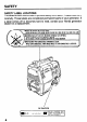
SAFETY SAFETY LABEL LOCATIONS The labels shown here contain important safety information. Please read them carefully. These labels are considered permanent parts of your generator. If a label comes off or becomes hard to read, contact your Honda generator dealer for a replacement. F.Y -_._.._ .._. ___ ._ _ WHECK FOR SPILLED FUEL OR FUEL LEAKS.
HONDA EXIOOO HONDA MOTOR CO., LTD. MADEIN JAPP~N A, n 00 NOT USE INDOORS. EXHAUST GAS CONTAINS lLUBRlCANT lCHANGE 0.431’ : INITIAL 20 HRS AN0 EVERY 100 HRS. GENERATOR POISONOUS CAREON MONOXIDE. OR ELECTRICAL APPLIANCES.
SAFETY INFORMATION Honda generators are designed to give safe and dependable service if operated according to instructions. Read and understand this owner’s manual before operating your generator. You can help prevent accidents by being familiar with your generator’s controls, and by observing safe operating procedures Operator Responsibility l Know how to stop the generator quickly in case of emergency. l Understand the use of all generator connections.
Fire and Burn Hazards The exhaust system gets hot enough to ignite some materials. - Keep the generator at least 3 feet (1 meter) away from buildings other equipment during operation. - Do not enclose the generator in any structure. - Keep flammable materials away from the generator. and The muffler becomes very hot during operation and remains hot for a while after stopping the engine. Be careful not to touch the muffler while it is hot. Let the engine cool before storing the generator indoors.
COMPONENT IDENTOFICATION FRAME SERIAL NUMBER CIRCUIT BREAKERS TOP C:OVER SPARK PLUG CAP \ ENGINE SWITCH FREQUENCY METER LEFT SIDE COVER AC RECEPTACLES GROUND TERMINAL ENGINE SERIAL NUMBER RECOIL STARTER GRIP OIL FILLER CAP Record the engine and frame serial numbers for your future reference.
CARRYING HANDLE FUEL GAUGE \ RIGHT SIDE COVER I FUEL TANK CAP \ CHOKE LEVER EXHAUST OUTLET AIR CLEANER CASE MUFFLER COVER 9
CONTROLS ENGIPJE SWITCH To start and stop the engine. Switch position: OFF: To stop the engine. ON: To run the engine. RECOIL STARTER To start the engine, pull the starter grip lightly until resistance briskly. is felt, then pull Do not allow the starter to snap back against the engine. Return it gently to prewent damage to the starter.
CHOKE LEVER The choke is used to provide an enriched fuel mixture when starting a cold engine. It can be opened and closed by operating the choke lever manually. Move the lever to the CLOSED position to enrich the mixture. iiOSED FREQUENCY METER The frequency meter indicates the frequency of the voltage produced by the generator.
GROlDND TERMINAL The generator ground terminal is connected to the frame of the generator, the metal non-current-carrying parts of the generator, and the ground terminals of each receptacle. Before using the ground terminal, consult a qualified electrician, electrical inspector or local agency having jurisdiction for local codes or ordinances that apply to the intended use of the generator.
OXIDATION CATALYTIC CONVERTER To meet EPAKARB Emission Control regulations, a catalytic converter is provided in the exhaust muffler. A thermal fuse is also installed in the exhaust muffler to prevent the catalytic converter from being overheated. If the muffler becomes too hot, the fuse comes into operation, stopping the engine automatically. If this occurs, take the generator to an authorized Honda servicing dealer to have the system inspected and the fuse replaced.
DC TERMINALS The DC terminals batteries. may ONLY be used for charging 12 volt automotive type The terminals are colored red to identify the positive (+) terminal and black to identify the negative (-) terminal. The battery must be connected to the generator DC terminals with the proper polarity (battery positive to generator red terminal and battery negative to the generator black terminal).
GENERATOR USE CONNECTIONS TO A BUILDING’S ELECTRICAL SYSTEM Connections for standby power to a building’s electrical system must be made by a qualified electrician. The connection must isolate the generator power from utility power, and must comply with all applicable laws and electrical codes. Improper connections to a building’s electrical system can allow electrical current from the generator to backfeed into the utility lines.
AC OPERATION 1. Start the engine (refer to page 24). 2. Plug in the appliance. Substantial overloading will switch off the circuit breaker. Marginal overloading may not switch off the circuit breaker, but it will shorten the service life of the generator. Be sure that all appliances are in good working order before connecting them to the generator. If an appliance begins to operate abnormally, becomes sluggish, or stops suddenly, turn off the generator engine switch immediately.
DC OPERATION The DC terminals batteries. CONNECTING may ONLY be used for charging THE BATTERY 12 volt automotive-type CABLES 1. Before connecting charging cables to a battery that is installed in a vehicle, disconnect the vehicle’s ground cable from the battery. The battery gives off explosive hydrogen gas during normal operation. A spark or open flame can cause the battery to explode with enough force to kill or seriously hurt you. Keep sparks and flames away.
An overloaded DC circuit, excessive current draw by the battery, or a wiring problem will trip the DC circuit breaker (PUSH button extends out). If this happens, wait a few minutes before pushing in the circuit breaker to resume operation. If the circuit breaker continues to go OFF, discontinue charging and see your authorized Honda generator dealer. DISCONNECTING THE BAlTERY CABLES 1. Stop the engine, 2. Disconnect terminal. the negative (-) battery cable from the generator negative (-) 3.
HIGH ALTITUDE OPERATION At high altitude, the standard carburetor air-fuel mixture will be too rich. Performance will decrease, and fuel consumption will increase. A very rich mixture will also foul the spark plug and cause hard starting. High altitude performance can be improved by specific modifications to the carburetor. If you always operate your engine at altitudes above 6,000 feet (1,800 meters), have your servicing dealer perform this carburetor modification.
PRE-OPERATION CHECK ENGINE OIL Engine oil is a major factor affecting engine performance and service life. Non-detergent and P-stroke engine oils will damage the engine and are not recommended. Check the oil level BEFORE EACH USE with the generator on a level surface with the engine stopped. Use 4-stroke motor oil that meets or exceeds the requirements for API service classification SF or SG.
FUEL Refueling Fuel tank capacity: 3.1 f? (0.82 US gal ) Check the fuel level gauge, and refill the tank if the fuel level is low. Gasoline is highly flammable and explosive. You can be burned or seriously l l l injured when handling fuel. Keep heat, sparks, and flame away. Handle fuel only outdoors. Wipe up spills immediately. Refuel in a well-ventilated area before starting the engine. If the engine has been running, allow it to cool. Refuel carefully to avoid spilling.
Fuel Recommendations Use unleaded gasoline with a pump octane rating of 86 or higher. This engine is certified to operate on unleaded gasoline. Unleaded gasoline produces fewer engine and spark plug deposits and extends exhaust system life. Never use stale or contaminated gasoline or an oil/gasoline getting dirt or water in the fuel tank. mixture. Avoid Occasionally you may hear a light “spark knock” or “pinging” (metallic rapping noise) while operating under heavy loads. This is no cause for concern.
Oxygenated Fuels Some conventional gasolines are being blended with alcohol or an ether compound. These gasolines are collectively referred to as oxygenated fuels. To meet clean air standards, some areas of the United States and Canada use oxygenated fuels to help reduce emissions. If you use an oxygenated fuel, be sure it is unleaded and meets the minimum octane rating requirement. Before using an oxygenated fuel, try to confirm the fuel’s contents.
STARTING/STOPPING STARTING THE ENGINE THE ENGINE 1. The generator may be hard to start if a load is connected. 2. Turn the choke lever to the CLOSE position. NOTE: Do not use the choke when the engine is warm. l 3. Turn the engine switch to the ON position. 4. Pull the starter grip lightly until you feel resistance, Return the starter grip gently. then pull briskly. 5. Turn the choke lever to the OPEN position as the engine warms up.
MAINTENANCE THE IMPORTANCE OF MAINTENANCE Good maintenance is essential for safe, economical, tion. It will also help reduce air pollution. and trouble-free opera- Improper maintenance, or failure to correct a problem before operation, can cause a malfunction in which you can be seriously hurt or killed. Always follow the inspection and maintenance schedules in this owner’s manual.
MAINTENANCE SAFETY Some of the most important safety precautions follow. However, we cannot warn you of every conceivable hazard that can arise in performing maintenance. Only you can decide whether or not you should perform a given task. Failure to properly follow maintenance instructions cause you to be seriously hurt or killed. Always follow the procedures and precautions and precautions can in the owner’s manual.
EMISSION CONTROL SYSTEM INFORMATION Source of Emissions The combustion process produces carbon monoxide, oxides of nitrogen, and hydrocarbons. Control of hydrocarbons and oxides of nitrogen is very important because, under certain conditions, they react to form photochemical smog when subjected to sunlight. Carbon monoxide does not react in the same way, but it is toxic.
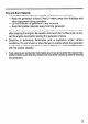
Problems That May Affect Emissions If you are aware of any of the following symptoms, have your engine inspected and repaired by your servicing dealer. l Hard starting l Rough idle. l Misfiring l Afterburning l Black exhaust 28 or stalling or backfiring after starting. under load. (backfiring). smoke or high fuel consumption.
Replacement Parts The emission control systems on your Honda engine were designed, built, and certified to conform with EPA and California emission regulations. We recommend the use of genuine Honda parts whenever you have maintenance done. These original-design replacement parts are manufactured to the same standards as the original parts, so you can be confident of their performance.
MAINTENANCE SCHEDULE First month REGULAR SERVICE PERIOD ITEM Perform at every indicated month or operating hour interval, whichever comes first. Check level l Engine oil Change Check . Air cleaner Clean Check-Clean l Spark plug Replace Clean Spark Arrester @ Combustion chamber and valves * 1 Valve clearance l Fuel tank and strainer Emission-related Each use 2OoHrrs. 507-Ls. (3) (3) Every year 100°Llrs.
TOOL KIT The tools supplied with the generator will help you to pet-form the owner maintenance procedures listed on the following pages. Always keep this tool kit with the generator.
ENGINE OIL CHANGE Drain the oil while the engine is warm to assure complete and rapid draining. 1. Remove the oil filler cap. 2. Turn the engine switch OFF and tilt the generator to drain the oil. 3. Refill with the recommended Oil capacity: oil {see page 20) and check the oil level. 0.43 k?(0.46 US qt, 0.38 Imp qt) OIL FILLER HOLE Oli FILLER CAP Wash your hands with soap and water after handling used oil.
AIR CLEANER SERVICE A dirty air cleaner will restrict air flow to the carburetor. To prevent carburetor malfunction, service the air cleaner regularly (page 30). Service more frequently when operating the generator in extremely dusty areas. Using gasoline or flammable solvent to clean the filter element can cause a fire or explosion. Use only soapy water or nonflammable solvent. 1 NOTICE 1 Never run the generator without the air cleaner. Rapid engine wear will result. 1.
SPARK PLUG SERVICE Recommended spark plugs: BPR4HS (NGK) To ensure proper engine operation, the spark plug must be properly gapped and free of deposits. If the engine has been running, the muffler will be very hot. Be careful not to touch the muffler. 1. Remove the spark plug cap. 2. Clean any dirt from around the spark plug base. 3. Use the wrench supplied in the tool kit to remove the spark plug. PLUG WRENCH 4. Visually inspect the spark plug. Discard it if the insulator is cracked or chipped.
6. Check that the spark plug washer is in good condition, and thread the spark plug in by hand to prevent cross-threading. 7. After the spark plug is seated, tighten with a spark plug wrench to compress the washer. If installing a new spark plug, tighten l/2 turn after the spark plug seats to compress the washer. If reinstalling a used spark plug, tighten l/8 - l/4 turn after the spark plug seats to compress the washer. The spark plug must be securely tightened.
SPARK ARRESTER MAINTENANCE If the generator has been running, the muffler will be very hot. Allow to cool before proceeding. The spark arrester must be serviced every 100 hours to keep it functioning designed. as 1. Remove the two 6 mm bolts and the two 6 mm cap nuts. Remove the cover. 6 mm BOLTS 6 mm CAP NUTS 2. Remove the two 6 mm nuts and the 6 mm bolt. Remove the muffler from the exhaust pipe carefully to avoid damaging the spark arrester screen.
3. Use a brush to remove carbon deposits from the spark arrester screen. Inspect the screen for holes, and replace it if necessary. NOTE: Take care not to damage the wire mesh. 4. Check the exhaust pipe gaskets; and the cover. replace if damaged.
TRAlNSPORTING/STORAGE When transporting the generator, turn the engine switch and the fuel valve OFF. Keep the generator level to prevent fuel spillage. Fuel vapor or spilled fuel may ignite. Contact with a hot engine or exhaust system can cause serious burns or fires. Let the engine cool before transporting or storing the generator. Take care not to drop or strike the generator when transporting. heavy objects on the generator. Before storing the unit for an extended period: 1.
1. Drain the carburetor by loosening the drain screw. Drain the gasoline into a suitable container. Gasoline is highly flammable and explosive. You can be burned or seriously . 0 0 injured when handling fuel. Keep heat, sparks, and flame away. Handle fuel only outdoors. Wipe up spills immediately. 2. Drain the fuel: a. With the engine switch ON, remove the fuel filler cap. b. Loosen the drain screw and drain the fuel into a suitable container. Retighten the screw. c. Move the engine switch to OFF. 3.
I TROUJBLESHOOTING When the engine will not start: ET Refill the fuel tank. NO IF NO 4 Turn the engine switch on. Add the recommended oil. NO Be sure there is no spilled fuel around the spark plug. “-‘“ed fuel may ignite. I YES r itill NO soark /CIeiioij :-------r-- To check: 1) Remove the rear cover and spark plug cap, and clean any dirt from around the spark plug. 2) Remove the spark plug and install the spark plug in the plug cap. 3) Set the plug side electrode on the cylinder head to ground.
No electricity at the AC receptacles: Is the AC circuit breaker on? Push the AC circuit breaker button in. YES Check the electrical appliance or equipment for any defects Take the generator to an authorized HONDA dealer. NO DEFECTS _ l DEFECTS * l Replace the electrical appliance or equipment. Take the electrical appliance or equipment to an electrical repair shop. No electricity at the DC terminals Is the DC circuit breaker on? NO YES Push the DC circuit breaker button in.
--t WIRING DIAGRAM I LIGHT GREEN --. 42 ‘E .
SPECIFICATIONS DIMENSIONS Length x Width x Height 430 x 285 x 390 mm (16.9 x 11.2 x 15.4 in) Dry Weight 26 kg (57.3 lb) ENGINE Model GlOl Engine Type 4-stroke, side valve, 1 cylinder Displacement [Bore x Stroke] 97.7 cc (5.96 cu in) [52 x 46 mm (2.05 x 1.81 in)] Compression 6.5 Ratio Engine Speed :1 3.600 r.p.m Cooling System Forced air coolina Ignition System Transistorized Oil Capacity 0.43 P (0.46 US qt, 0.38 Imp qt) Fuel Tank Capacity 3.1 Q (0.
WARRANTY SERVICE INFORIMATION Honda power equipment dealership personnel are trained professionals. They should be able to answer any question you may have. If you encounter a problem that your dealer does not solve to your satisfaction, please discuss it with the dealership’s management. The Service Manager or General Manager can help. Almost all problems are solved in this way.
Current customer service contact information: United States, Puerto Rico, and U.S. Virgin Islands: Honda Power Equipment dealership personnel are trained professionals. They should be able to answer any question you may have. If you encounter a problem that your dealer does not solve to your satisfaction, please discuss it with the dealership's management. The Service Manager or General Manager can help. Almost all problems are solved in this way.
INDEX COMPONENT CONTENTS IDENTIFICATION . . . .... . .. . . .. . .. . .. . . .. . .. . . .. . .. . . .. . .. . . .. . . .. . . .. . .. . .. . .. . 8 .. . . .. .. . . .. . .. . .. . .. . .. . .. . .. . . .. . . ... .. .. . . .. . .. . .. . . .. . .. . .. . . .. . .. . . .. . .. . .. . . .. . .. . . .. .. . . . 2 CONTROLS & FEATURES ...................................................................... AC Circuit Breaker ...............................................................................
PRE-OPERATION CHECK.. .................................................................... Engine Oil.. .......................................................................................... Fuel ..................................................................................................... SAFETY ..................................................................................................... Safety Information .................................................................................
I MEMO 47
MEMO 48