TILLER FE500・F501 OWNER'S MANUAL MANUEL DE L'UTILISATEUR BEDIENUNGSANLEITUNG MANUAL DE EXPLICACIONES MANUALE DELL'UTENTE
Honda F501·FE500 OWNER’S MANUAL Original instructions MANUEL DE L’UTILISATEUR Notice originale BEDIENUNGSANLEITUNG Originalbetriebsanleitung MANUAL DE EXPLICACIONES Manual original MANUALE DELL’UTENTE Istruzioni originali The ‘‘e-SPEC’’ mark symbolizes environmentally responsible technologies applied to Honda power equipment, which contains our wish to ‘‘preserve nature for generations to come.
Thank you for purchasing a Honda tiller. This manual covers operation and maintenance of the F501 and FE500 tillers. All information in this publication is based on the latest product information available at the time of printing. Honda Motor Co., Ltd. reserves the right to make changes at any time without notice and without incurring any obligation. No part of this publication may be reproduced without written permission.
Disposal To protect the environment, do not dispose of this product, battery, engine oil, etc. carelessly by leaving them in the waste. Observe the local laws and regulations or consult your authorized Honda dealer for disposal.
CONTENTS 1. SAFETY INSTRUCTIONS.................................................................... 3 2. SAFETY LABEL LOCATIONS.............................................................. 9 CE mark location............................................................................. 11 3. COMPONENT IDENTIFICATION ...................................................... 13 4. PRE-OPERATION CHECK ................................................................. 17 5. STARTING THE ENGINE ......................
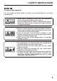
1. SAFETY INSTRUCTIONS To ensure safe operation− For your safety and the safety of others, pay special attention to these precautions: Honda tiller is designed to give safe and dependable service if operated according to instructions. Read and understand the Owner’s Manual before operating the tiller. Failure to do so could result in personal injury or equipment damage. Exhaust contains poisonous carbon monoxide, a colorless, odorless gas.
Gasoline is extremely flammable and is explosive under certain conditions. Do not smoke or allow flames or sparks in the area where the tiller is refueled or where gasoline is stored. Do not overfill the fuel tank, and make sure the fuel tank cap is closed securely after refueling. Refuel in a well-ventilated area with the engine stopped. Operator responsibility Keep the tiller in good operating condition. Operating a tiller in poor or questionable condition could result in serious injury.
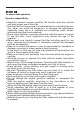
To ensure safe operation− Operator responsibility Read the owner’s manual carefully. Be familiar with the controls and their proper use of the tiller. Use the tiller for the purpose it is intended that is, cultivating the soil. Any other use could be dangerous or damage the equipment, especially never use it to cultivate soil containing rocks, stones, wires and any other hard materials. Never allow children or people unfamiliar with this owner’s manual to use the tiller.
To ensure safe operation− Operator responsibility Stop the engine in the following cases: −Whenever you leave the tiller unattended. −Before refueling When stopping the engine, move the throttle lever to the LOW position, then turn the engine switch OFF. If the fuel valve is equipped on the tiller, be sure to turn the fuel valve OFF. Keep all nuts, bolts and screws tight to be sure the tiller is in safe working condition.
To ensure safe operation− Fire and burn hazard Gasoline is extremely flammable, and gasoline vapor can explode. Use extreme care when handling gasoline. Keep gasoline out of reach of children. Add fuel before starting the engine. Never remove the cap of the fuel tank or add gasoline while the engine is running or when the engine is hot. Refuel in a well-ventilated area with the engine stopped. Refuel outdoors only and do not smoke while refueling or handling fuel. Allow the engine to cool before refueling.
To ensure safe operation− Carbon monoxide poisoning hazard Exhaust contains poisonous carbon monoxide, a colorless and odorless gas. Breathing exhaust can cause loss of consciousness and may lead to death. If you run the engine in an area that is confined or even partially enclosed, the air you breathe could contain a dangerous amount of exhaust gas. To keep exhaust gas from building up, provide adequate ventilation. Replace faulty muffler.
2. SAFETY LABEL LOCATIONS These labels warn you of potential hazards that can cause serious injury. Read the labels and safety notes and precautions described in this manual carefully. If a label comes off or becomes hard to read, contact your Honda dealer for a replacement.
FE500 READ OWNER’S MANUAL EXHAUST CAUTION FUEL CAUTION CUTTING DANGER 10
CE mark location F501 CE MARK Name and address of manufacturer Sales agency and address Description code Year of manufacture Frame serial number Machine mass (standard specification) Engine net power 11
FE500 CE MARK Name and address of manufacturer Sales agency and address Description code Year of manufacture Frame serial number Machine mass (standard specification) Engine net power 12
3.
HANDLE BAR AIR CLEANER SPARK PLUG CHOKE LEVER STARTER GRIP HITCH PIN HITCH ATTACHMENT DRAG BAR A FUEL VALVE DRAG BAR B SEDIMENT CUP HITCH BOX CARBURETOR DRAIN KNOB TRANSMISSION OIL FILLER CAP Record the frame serial number in the space below. You will need this number when ordering parts.
FE500 THROTTLE LEVER ENGINE SWITCH HANDLEBAR FIXING LEVER MUFFLER CLUTCH LEVER FUEL TANK CAP BELT COVER ROTOR (equipped type) FRONT WHEEL (equipped type) ENGINE OIL FILLER CAP ENGINE OIL DRAIN BOLT 15
HANDLE BAR SPARK PLUG AIR CLEANER CHOKE LEVER STARTER GRIP FUEL VALVE DRAG BAR SEDIMENT CUP CARBURETOR DRAIN KNOB TRANSMISSION OIL FILLER CAP Record the frame serial number in the space below. You will need this number when ordering parts.
4. PRE-OPERATION CHECK Place the tiller on a firm level surface and hold the tiller level (i.e. with the rotary tines, front wheel (if equipped) and drag bar (see page 18 )). Stop the engine before starting service of the tiller. Servicing the tiller on an unstable surface of the ground or without stopping the engine can cause injury and/or equipment damage. Daily inspection and service of tiller is essential for safe and reliable operation. Perform the following check before operation. 1.
5. Engine oil Running the engine with insufficient oil can cause serious engine damage. 1. Place the tiller on the level surface and hold the tiller level by placing wooden blocks under the front wheel (if equipped) and drag bar as shown. 2. Remove the oil filler cap and wipe the dipstick clean. 3. Insert the dipstick into the oil filler neck, but do not screw it in.
4. If the level is low, fill to the top of the oil filler neck with the recommended oil. Recommended oil Use 4-stroke motor oil that meets or exceeds the requirements for API service category SE or later (or equivalent). Always check the API service label on the oil container to be sure it includes the letters SE or later (or equivalent). Using nondetergent oil or 2-stroke engine oil will shorten the engine’s service life. SAE 10W-30 is recommended for general use.
6. Transmission gear oil Place the tiller on a level surface and remove the oil filler cap. The oil should be level with the lower edge of the oil filler hole. Add high quality engine oil if the level is low.
7. Air cleaner Never run the engine without the air cleaner. Rapid engine wear will result. Remove the air cleaner cover. Check the air cleaner elements for dirt or obstruction. Clean if necessary (see page 45 ).
8. Fuel Check the fuel level, and refill the tank if the fuel level is low. Use unleaded gasoline with a Research Octane Number of 91 or higher (a Pump Octane Number of 86 or higher). Never use stale or contaminated gasoline or an oil/gasoline mixture. Avoid getting dirt or water in the fuel tank. Gasoline is extremely flammable and is explosive under certain conditions. Refuel in a well-ventilated area with the engine stopped.
Gasoline spoils very quickly depending on factors such as light exposure, temperature and time. In worst cases, gasoline can be contaminated within 30 days. Using contaminated gasoline can seriously damage the engine (carburetor clogged, valve stuck). Such damage due to spoiled fuel is disallowed from coverage by the warranty. To avoid this please strictly follow these recommendations: Only use specified gasoline (see page 22 ). Use fresh and clean gasoline.
9. Tools and Attachments To install a tool or attachment on the tiller, follow the instructions furnished with the tool or attachment. Ask your Honda dealer for advice if you encouter any problem or difficulty in installing a tool or attachment.
10.Clutch lever operation (check and cleaning) Check that the clutch lever operates smoothly. Check that there are no foreign objects (such as sand, soil, twigs, etc.) on the roller surface. If the clutch lever roller does not move smoothly or if it is dirty, clean the clutch lever and roller (see page 26 ). Do not apply any oil or cleaner liquid to the clutch lever roller. Oil or cleaner liquid will attract dirt and foreign objects.
1. Pull off the snap pin from the lever fulcrum pin. 2. By holding the clutch lever, pull out the lever fulcrum pin. Detach the clutch lever and the wave washer. 3. Remove any dirt or foreign objects. Wipe off and clean the roller surface of the clutch lever. 4. Set the inside and upper side direction of the wave washer as shown in the illustration. With the wave washer set in this position, attach the clutch lever and slide in the lever fulcrum pin. 5.
5. STARTING THE ENGINE Be sure the clutch is disengaged and the shift lever (except FE500) is in the neutral position to prevent sudden uncontrolled movement when the engine starts. The clutch is engaged by pulling in the clutch lever and disengaged by releasing the lever. 1. Turn the fuel valve ON. Check for tighteness of drain knob. FUEL VALVE DRAIN KNOB ON 2. Close the choke lever. Do not use the choke if the engine is warm or the air temperature is high.
3. Turn the engine switch ON. ON ENGINE SWITCH 4. Align the mark ‘‘△’’ on the throttle lever with the mark ‘‘○’’ (START position) as shown.
5. Pull the starter grip lightly until you feel resistance, then pull briskly in the direction of the arrow as shown. STARTER GRIP Hold the handle with your left hand and start the engine by pulling out the starter grip. Direction to pull Do not allow the starter grip to snap back against the engine. Return it gently to prevent damage to the starter. 6. As the engine warms up, gradually open the choke.
Carburetor Modification for High Altitude Operation At high altitude, the standard carburetor air-fuel mixture will be too rich. Performance will decrease, and fuel consumption will increase. A very rich mixture will also foul the spark plug and cause hard starting. Operation at an altitude that differs from that at which this engine was certified, for extended periods of time, may increase emissions. High altitude performance can be improved by specific modifications to the carburetor.
6. TILLER OPERATION 1. Handlebar position adjustment Before adjusting the handlebar, place the tiller on the firm level ground to prevent the handle from collapsing accidentally. To adjust the handlebar height, loosen the handlebar fixing lever, move the handlebar to a desired position and tighten the lever. HANDLEBAR FIXING LEVER If the handlebar angle adjustment is needed, loosen the handlebar fixing lever, move the handlebar to a required position and tighten the lever.
2. Tilling depth adjustment F501 Install the hitch attachment in the hitch box with a hitch pin. The tilling depth adjustment can be made as follows: Remove the lock pin and pin, loosen the lock nuts and bolts securing the drag bars A and B, and slid the drag bars up or down as necessary. After adjustment, tighten the bolts and lock nuts securely.
FE500 The tilling depth adjustment can be made by removing the pin and lock pin and sliding the drag bar up or down as necessary.
3. Clutch operation The clutch engages and disengages the power from the engine to the transmission. When the clutch lever is squeezed, the clutch is engaged and power is transmitted to the tool. When the lever is released, the clutch is disengaged and power is not transmitted to the tool. Reduce engine rpm before operating main clutch operation.
4. Gear selection (F501 only) The transmission can be shifted into two forward speeds and one reverse speed. The shift lever should be operated in accordance with the attached gear shifting plate. GEAR SHIFTING PLATE FORWARD 1 REVERSE FORWARD 2 NEUTRAL NEUTRAL SHIFT LEVER Gear shifting 1. Return the throttle lever to the extreme right. 2. Release the clutch lever to disengage the clutch. 3. Move the shift lever to the desired gear position.
5. Use of the hitch box (F501 only) Install the hitch attachment in the hitch box with a hitch pin. (Hitch pin clip snaps into relief in hitch pin to retain pin.
6. Front wheel (Equipped type) Use a front wheel to move the tiller on road. Lift the handlebars up and ground the front wheel. When the tiller is used in the field, move the wheel up. FRONT WHEEL UP POSITION (When used in the field) DOWN POSITION (When moved on road) F501 Move the front wheel up by replacing the pin. FE500 Move the front wheel up by shifting the pivot at the front wheel fork into the upper notch.
7. Handling tips If the tiller tends to move forward rapidly, push down on the handlebars to allow the drag bar to penetrate the soil and slow the forward motion on the tiller. Continue to press down until the tiller tines have dug to a desired depth that allows easy tiller handling. If the tines dig in but the tiller will not move forward, ease up on the handlebars and move the handlebars from side-to-side. If the tiller still digs in but will not move forward, raise the drag bar up a hole.
8. Normal operating angle Lower the handle slightly so the front of the machine is raised about 6 ∼ 8°. 6∼8° To get the maximum advantage from the tiller, try to hold the machine at the angle shown while you are tilling the ground: Do not use the tiller with a rotor whose diameter is in excess of 325 mm (12.8 in). Operating the tiller on grades could cause the tiller to tip over. Allowing any one to operate this tiller without proper instruction may result in injury. Wear sturdy, full coverage footgear.
7. STOPPING THE ENGINE In an emergency: Turn the engine switch OFF. OFF OFF OFF OFF ENGINE SWITCH In normal use: 1. Release the clutch lever to DISENGAGED position and shift lever is in neutral position.
2. Move the throttle lever fully to the right. THROTTLE LEVER 3. Turn the engine switch OFF. OFF OFF OFF OFF ENGINE SWITCH 4. Turn the fuel valve to the OFF position.
8. MAINTENANCE The purpose of the maintenance schedule is to keep the tiller in the best operating condition. Inspect or service as scheduled in the table below. Shut off the engine before performing any maintenance. Exhaust contains poisonous carbon monoxide gas; Exposures cause loss of consciousness and may lead to death. If the engine must be run, make sure the area is well ventilated. Use only genuine Honda parts or their equivalent for maintenance or repair.
Maintenance schedule REGULAR SERVICE PERIOD (3) Perform at every indicated month or o per ati ng h our int erv al, whichever comes first.
1. Changing oil Change the oil when the engine is warm to assure rapid and complete draining. 1. Remove the oil filler cap and drain bolt to drain the oil. 2. Reinstall the drain bolt and tighten it securely. 3. Refill with the recommended oil (see page 19 ) and check the oil level. 4. Reinstall the oil filler cap/dipstick. Oil capacity: 0.58 L (0.61 US qt, 0.51 lmp qt) OIL FILLER CAP/DIPSTICK UPPER LIMIT DRAIN BOLT SEALING WASHER Wash your hands with soap and water after handling used oil.
2. Air cleaner service A dirty air cleaner will restrict air flow to the carburetor. To prevent carburetor malfunction, service the air cleaner regularly. Service more frequently when operating the engine in extremely dusty areas. Never use gasoline or low flash point solvents for cleaning the air cleaner element. A fire or explosion could result. Never run the engine without the air cleaner. Rapid engine wear will result. 1. Remove the wing nut and the air cleaner cover.
3. Sediment cup cleaning Gasoline is extremely flammable and is explosive under certain conditions. Do not smoke or allow flames or sparks in the area. Turn the fuel valve to the OFF position and remove the sediment cup and the O-ring. Wash the sediment cup in solvent, dry it thoroughly. Place the O-ring in the fuel valve, and install the sediment cup. Tighten the sediment cup securely. Turn the fuel valve ON and check for leaks.
4. Spark plug service Recommended spark plug: BPR5ES (NGK) W16EPR-U (DENSO) To ensure proper engine operation, the spark plug must be properly gapped and free of deposits. 1. Remove the spark plug cap. Use the spark plug wrench to remove the spark plug. If the engine has been running, the muffler will be very hot. Be careful not to touch the muffler. SPARK PLUG WRENCH SPARK PLUG CAP 2. Visually inspect the spark plug. Discard it if the insulator is cracked or chipped.
4. Check that the spark plug washer is in good condition and thread the spark plug in by hand to prevent cross-threading. SPARK PLUG WRENCH 5. After the spark plug is seated, tighten with a spark plug wrench to compress the washer. After seating it by hand, tighten a new spark plug 1/2 turn with the wrench to compress the washer. If you are reusing a plug, it should only take 1/8−1/4 turn. The spark plug must be securely tightened.
5. Throttle cable adjustment Measure the free play at the lever tip. Free play: 5−10 mm (0.2−0.4 in) THROTTLE LEVER FREE PLAY: 5−10 mm (0.2−0.4 in) If the free play is incorrect, loosen the lock nut and turn the adjusting bolt in or out as required.
9. TRANSPORTING/STORAGE When transporting the tiller, turn the fuel valve OFF and keep the tiller level to prevent fuel spillage. Fuel vapor or spilled fuel may ignite. Before storing the unit for an extended period: 1. Be sure the storage area is free of excessive humidity and dust. 2. Drain the fuel: Gasoline is flammable and explosive under certain conditions. Do not smoke or allow flames or sparks near the equipment while draining fuel. a.
3. Pull the starter grip until resistance is felt. Continue pulling until the notch on the starter pulley aligns with the hole on the recoil starter (see illustration below). At this point, the intake and exhaust valves are closed, and this will help to the engine from internal corrosion. Align the notch on the starter pulley with the hole at the top of the recoil starter. 4. Change engine oil. 5. Apply oil or grease to the pivot points of the clutch lever. ROLLER SURFACE CLUTCH LEVER 6.
10. TROUBLESHOOTING When the engine will not start: 1. Is there enough fuel? 2. Is the fuel valve on? 3. Is the engine switch on? 4. Is gasoline reaching the carburetor? To check, loosen the drain knob with the fuel valve on. Fuel should flow out freely. Retighten drain knob. If any fuel is spilled, make sure the area is dry before starting the engine. Spilled fuel or fuel vapor may ignite. FUEL VALVE DRAIN KNOB ON 5. Is the spark plug in good condition? Remove and inspect the spark plug.
11. SPECIFICATIONS F501-GE Model Description code F501-HE FZAZ Dimensions and weight Model Length Width Height Dry mass [weight] F501-GE F501-HE 1,600 mm (63.0 in) 1,385 mm (54.5 in) 610 mm (24.0 in) 980 mm (38.6 in) 49 kg (108 lbs) 46 kg (101 lbs) Engine Model Type Displacement Bore × Stroke Ignition system Spark plug Oil capacity Fuel tank capacity GX160 4-stroke, 1-cylinder, OHV, forced air cooled 163 cm (9.9 cu-in) 68.0 × 45.0 mm (2.68 × 1.
Model Description code FE500-EI FE500-EIT FARJ Dimensions and weight Model Length Width Height Dry mass [weight] FE500-EI FE500-EIT 1,460 mm (57.5 in) 925 mm (36.4 in) 600 mm (23.6 in) 990 mm (39.0 in) 54 kg (119 lbs) 41 kg (90 lbs) Engine Model Type Displacement Bore × Stroke Ignition system Spark plug Oil capacity Fuel tank capacity GX160 4-stroke, 1-cylinder, OHV, forced air cooled 163 cm (9.9 cu-in) 68.0 × 45.0 mm (2.68 × 1.77 in) Transistor magneto BPR5ES (NGK) , W16EPR-U (DENSO) 0.58 L (0.
MAJOR Honda DISTRIBUTOR ADDRESSES For further information, please contact Honda Customer Information Centre at the following address or telephone number: ADRESSES DES PRINCIPAUX DISTRIBUTEURS Honda Pour plus d’informations, s’adresser au Centre d’informations clients Honda à l’adresse ou numéro de téléphone suivants: ADRESSEN DER HAUPT-Honda-VERTEILER Weitere Informationen erhalten Sie gerne vom HondaKundeninformationszentrum unter der folgenden Adresse oder Telefonnummer: DIRECCIONES DE LOS PRINCIPALES
AUSTRIA CROATIA FINLAND Honda Motor Europe (North) Hongoldonia d.o.o. OY Brandt AB. Hondastraße 1 Jelkovecka Cesta 5 Tuupakantie 7B 2351 Wiener Neudorf 10360 Sesvete − Zagreb 01740 Vantaa Tel. : +43 (0)2236 690 0 Tel. : +385 1 2002053 Tel. : +358 20 775 7200 Fax : +43 (0)2236 690 480 Fax : +385 1 2020754 Fax : +358 9 878 5276 http://www.honda.at http://www.hongoldonia.hr http://www.brandt.fi jure@hongoldonia.
HUNGARY MALTA PORTUGAL Motor Pedo Co., Ltd. The Associated Motors Honda Portugal, S.A. Kamaraerdei ut 3. Company Ltd. Rua Fontes Pereira de Melo 16 2040 Budaors New Street in San Gwakkin Road Abrunheira, 2714-506 Sintra Tel. : +36 23 444 971 Mriehel Bypass, Mriehel QRM17 Tel. : +351 21 915 53 33 Fax : +36 23 444 972 Tel. : +356 21 498 561 Fax : +351 21 915 23 54 http://www.hondakisgepek.hu Fax : +356 21 480 150 http://www.honda.pt info@hondakisgepek.hu honda.produtos@honda-eu.
SERBIA & MONTENEGRO Tenerife province UKRAINE (Canary Islands) Honda Ukraine LLC Bazis Grupa d.o.o. Automocion Canarias S.A. 101 Volodymyrska Str. - Build. 2 Grcica Milenka 39 Carretera General del Sur, KM. 8,8 Kyiv 01033 11000 Belgrade 38107 Santa Cruz de Tenerife Tel. : +380 44 390 1414 Tel. : +381 11 3820 295 Tel. : + 34 (922) 620 617 Fax : +380 44 390 1410 Fax : +381 11 3820 296 Fax : +34 (922) 618 042 http://www.honda.ua http://www.hondasrbija.co.rs http://www.aucasa.com CR@honda.
"EC Declaration of Conformity" CONTENT OUTLINE "CE-Déclaration de conformité" DESCRIPTION DE TABLE DES MATIERES "EU-Konformitätserklärung" INHALTSÜBERSICHT DESCRIPCIÓN GENERAL DEL CONTENIDO DE LA "Declaración de Conformidad CE" DESCRIZIONE DEL CONTENUTO DELLA "Dichiarazione CE di Conformità" EC Declaration of Conformity 1.
Français. (French) Déclaration CE de Conformité 1. Le sous signé, Piet Renneboog, de la part du représentant autorisé, déclare que la machine décrit ci-dessous répond à toutes les dispositions applicables de * Directive Machine 2006/42/CE * Directive 2004/108/CE sur la compatibilité électromagnétique 2. Description de la machine a) Denomination générique : Motobineuse b) Fonction : préparer le sol c) Nom Commercial d) Type e) Numéro de série 3. Constructeur 4. Représentant autorisé 5.
Português ( Portuguese ) Declaração CE de Conformidade 1. O abaixo assinado, Piet Renneboog, declara deste modo, em nome do mandatário, que o máquina abaixo descrito cumpre todas as estipulações relevantes da: * Directiva 2006/42/CE de máquina * Directiva 2004/108/CE de compatibilidade electromagnética 2. Descrição da máquina a) Denominação genérica : Motoenxada b) Função : preparar o solo c) Marca d) Tipo e) Número de série 3. Fabricante 4. Mandatário 5. Referência a normas harmonizadas 6.
Lietuvių kalba (Lithuanian) EB atitikties deklaracija 1. Įgaliotojo atstovo vardu pasirašęs Piet Renneboog patvirtina, kad žemiau aprašyta mašina atitinka visas išvardintų direktyvų nuostatas: * Mechanizmų direktyva 2006/42/EB * Elektromagnetinio suderinamumo direktyva 2004/108/EB 2. Prietaiso aprašymas a) Bendras pavadinimas : Motorinis kauptukas b) Funkcija : dirvos paruošimas c) Komercinis pavadinimas d) Tipas e) Serijos numeris 3. Gamintojas 4. Įgaliotasis atstovas 5. Nuorodos į suderintus standartus 6.
K5:F501 3QV31610 00X3Q-V31-6101 KS C Honda Motor Co., Ltd.