OWNER'S MANUAL Mini-Tiller FG100 ¿Necesita un manual en Español? Vea a la página 44. ©1997 American Honda Motor Co., Inc. All Rights Reserved See page 28 for instructions on assembling your FG100 Mini-Tiller.
B WARNING: B The engine exhaust from this product contains chemicals known to the State of California to cause cancer, birth defects, or other reproductive harm. Keep this owner’s manual handy so you can refer to it at any time. This should remain with the tiller if resold. The information and specifications included in this publication were in effect at the time of approval for printing. American Honda Motor Co., Inc.
FG100 TILLER INTRODUCTION Congratulations on your selection of a Honda Harmony FG100 Tiller. We are certain you will be pleased with your purchase of one of the finest tillers on the market. We want to help you get the best results from your new tiller and to operate it safely. This manual contains the information on how to do that; please it carefully. As you read this manual, you will find information preceded by a NOTICE symbol.
FG100 TILLER A FEW WORDS ABOUT SAFETY Your safety and the safety of others are very important. And using this tiller is an important responsibility. To help you make informed decisions about safety, we have provided operating procedures and other information on labels in this manual. This information alerts you to potential hazards that could hurt you or others. Of course, it is not practical or possible to warn you about all the hazards associated with operating or maintaining a tiller.
FG100 TILLER CONTENTS SAFETY ............................................................4 IMPORTANT SAFETY INFORMATION.........4 ATTACHMENTS AND MODIFICATIONS ......5 IMPORTANT MESSAGE TO EMPLOYERS..5 IMPORTANT MESSAGE TO PARENTS .......5 SAFETY LABEL LOCATIONS .......................6 CONTROLS ......................................................7 COMPONENT IDENTIFICATION ..................7 DESCRIPTION OF CONTROLS....................8 Throttle Lever . . . Engine Switch . . .
SAFETY IMPORTANT SAFETY INFORMATION Most accidents with this product can be prevented if you follow all instructions in this manual and on the product. The most common hazards, according to accident statistics, are discussed below, along with the best way to protect yourself and others. Honda Tiller Usage Honda tillers are designed to give safe and dependable service if operated according to instructions and intended use.
SAFETY ATTACHMENTS AND MODIFICATIONS Do not make any modifications to your tiller. Modifying your tiller, or installing non-Honda attachments, can make your tiller unsafe. If you need attachments for your tiller, use only genuine Honda attachments. These products have been designed for your tiller and are covered by warranty. Non-Honda attachments are usually designed for universal applications.
SAFETY SAFETY LABEL LOCATIONS The labels shown here contain important safety information. Please read them carefully. These labels are considered permanent parts of your Honda tiller. If a label comes off or becomes hard to read, immediately contact a Honda tiller servicing dealer for a replacement label. DISE NGAGE E NGAGE HOT / CHAUD HOLD HERE WHEN STARTING CONTACT WITH ROTATING TINES CAN CAUSE SERIOUS INJURY. KEEP HANDS, FEET AND CLOTHING AWAY WHILE ENGINE IS RUNNING.
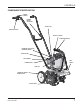
CONTROLS COMPONENT IDENTIFICATION ENGINE SWITCH HANDLE HEIGHT ADJUSTER SPARK PLUG THROTTLE LEVER RECOIL STARTER CARRYING HANDLE ENGINE OIL FILLER CAP/ ENGINE OIL DRAIN CHOKE LEVER AIR CLEANER TINE SHIELD PRIMING BULB FUEL CAP TRANSPORT WHEEL OR DRAG BAR TILLING TINES FG100 TILLER 7
CONTROLS DESCRIPTION OF CONTROLS Throttle Lever ENGINE SWITCH THROTTLE LEVER The throttle lever controls engine speed and tiller tine rotation. Pulling the throttle lever towards the grip increases the engine speed which causes the tines to turn. Releasing the throttle lever reduces engine speed and stops the tiller tines from turning. The tiller will have the greatest tilling force at maximum engine speed. At idle, the tilling tines should stop rotating.
CONTROLS Transport Wheels CARRYING HANDLE The transport wheels are used to move the tiller around. Before tilling, the transport wheels must be removed and the drag bar installed in their place. RECOIL STARTER Carrying Handle The carrying handle rubber grip is used to hold the tiller when starting the engine. TRANSPORT WHEELS The carrying handle can be used to load/unload the tiller, and to assist in certain engine maintenance procedures.
BEFORE OPERATION ARE YOU READY TO OPERATE THE TILLER? Your safety is your responsibility. A little time spent in preparation will significantly reduce your risk of injury. Knowledge Read and understand this manual. Know what the controls do and how to operate them. Familiarize yourself with the tiller and its operation before you begin to use it. Know what to do in case of emergencies. Physical and Mental Readiness You must be alert and in good physical condition to operate the tiller.
BEFORE OPERATION IS YOUR WORKING AREA READY? Objects thrown by the tiller can cause serious injury. Be especially careful when crossing gravel drives, walks or roads. Before operating the tiller, carefully inspect the area, and remove all objects that could be thrown by, or entangled in, the tilling attachment, such as rocks, broken glass, nails, wire, or string. Never operate the tiller without good visibility or light. Clear the area of children, bystanders, and pets.
OPERATION SAFETY PRECAUTIONS Before operating the tiller for the first time, please review the IMPORTANT SAFETY INFORMATION (see page 4) and the chapter titled BEFORE OPERATION (see page 10). Even if you have operated other tillers, take time to become familiar with the operation of this tiller’s controls and handling. For your safety, avoid starting or operating the engine in an enclosed area, such as a garage.
OPERATION Starting The Engine 1. Move the engine switch to the ON position. 2. To start a cold engine, move the choke lever to the CLOSED (E) position. To restart a warm engine, leave the choke lever in the OPEN position. 3. To start a cold engine, or after refueling an engine that has run out of fuel, press the priming bulb repeatedly until fuel can be seen in the clear plastic fuel-return tube. To restart a warm engine, it is not necessary to press the priming bulb. 4.
OPERATION TILLER OPERATION 1. Install the drag bar (see page 12). Honda recommends using the drag bar when tilling. The tiller can be difficult to control without the drag bar installed. 2. Adjust the handlebar to a comfortable position (see page 12) (waist height for normal tilling operation). 3. Set the tilling depth by moving the drag bar up or down (see page 12). 4. 5. 6. 7. The ideal height of the drag bar will depend on the type of soil being tilled, and soil conditions at the time of tilling.
OPERATION LOCK PIN Tilling In Rocky Soil [a] If you are tilling in stony or rocky soil, and experience continual rock jams between tines, set the tiller tines in the rocky soil pattern to help alleviate the problem. 1. Stop the engine (see page 13). 2. Disconnect the spark plug wire (see page 22). 3. Tip the tiller forward on the carrying handle as shown. 4. Remove the lock pins from the left and right tine shafts by turning them UP [a] and pulling them OUT [b]. 5. Clean the tine shafts. 6.
OPERATION OHV Angled portion edge should enter the soil View from the rear. LOCK PIN B C Narrow Cultivating The two outer tines can be removed to give you a narrower cultivating width. This width is approximately 6 inches. This will give you the ability to get between very closely spaced plants. In order to do this, pull the lock pin out of the hole in the end of the tine shaft. Slide the outside tine set off the tine shaft and place a tine spacer, included with your tiller, over the tine shaft.
MAINTENANCE & ADJUSTMENTS SERVICING YOUR HONDA TILLER THE IMPORTANCE OF MAINTENANCE MAINTENANCE SAFETY Good maintenance is essential for safe, economical, and trouble-free operation. It will also help reduce air pollution. Some of the most important safety precautions follow. However, we cannot warn you of every conceivable hazard that can arise in performing maintenance. Only you can decide whether or not you should perform a given task.
MAINTENANCE & ADJUSTMENTS MAINTENANCE SCHEDULE REGULAR SERVICE PERIOD (3) ITEM • Perform at every indicated interval Engine Oil Check Before Each Use • Air Filter Spark Plug Every year or 100 Hrs Every 2 years or 200 Hrs 19 O O 19 20 O (1) 21 O Check-Clean Throttle Cable Check O Cooling Fins Check O Refer to page number 21 24 O 24 Spark Arrester Clean O 23 • Fuel Tank Clean O 26 • Fuel Filter Check O 26 Clutch Shoes Check • Idle Speed Check-Adjust O (2) 24 • V
MAINTENANCE & ADJUSTMENTS Engine Oil Level Check CARRYING HANDLE Check the engine oil level before each use, or every 10 hours if operated continuously. Tip the tiller on its carrying handle, on a level surface, with the engine stopped and in an upright position. 1. Tip the tiller on its carrying handle as shown. 2. Remove the oil filler cap/dipstick and wipe it clean. 3. Insert and remove the dipstick without screwing it into the filler opening. Check the oil level shown on the dipstick. 4.
MAINTENANCE & ADJUSTMENTS Engine Oil Recommendations Oil is a major factor affecting performance and service life. Use 4-stroke automotive detergent oil. SAE 10W-30 is recommended for general use. Other viscosities shown in the chart may be used when the average temperature in your area is within the recommended ranges. –20 –30 – 2 0 –10 20 40 0 10 0 80 60 20 100 F 30 400C AMBIENT TEMPERATURE The SAE oil viscosity and service classification are in the API label on the oil container.
MAINTENANCE & ADJUSTMENTS Air Filter Cleaning A dirty air filter restricts air flow to the carburetor, reducing engine performance. If you operate the engine in very dusty areas, clean the air filter after each refueling. 1. Remove the air filter (see page 20). 2. Clean the air filter in warm soapy water, rinse, and allow to dry thoroughly. Or, clean in nonflammable solvent and allow to dry. 3. Dip the air filter in clean engine oil, then squeeze out all excess oil.
MAINTENANCE & ADJUSTMENTS Spark Plug Service Recommended spark plugs: C5HSB or CR5HSB (NGK) U16FS-UB or U16FSR-UB (DENSO) SPARK PLUG SPARK PLUG CAP NOTICE Incorrect spark plugs can cause engine damage. 1. Disconnect the spark plug cap, and remove any dirt from around the spark plug area. 2. Remove the spark plug with a 5/8-inch spark plug wrench. 3. Inspect the spark plug. Replace it if the electrodes are worn, or if the insulator is cracked or chipped.
MAINTENANCE & ADJUSTMENTS RECOIL STARTER Spark Arrester Service The spark arrester must be serviced every 100 hours to keep it functioning as designed. If the engine has been running, the muffler will be very hot. Allow the muffler to cool before servicing the spark arrester. 1. Remove the four 5 x 18 mm bolts from the recoil starter, and remove the recoil starter. 2. Disconnect the spark plug cap from the spark plug.
MAINTENANCE & ADJUSTMENTS Cooling Fin Inspection Inspect the engine cooling fins. Clean out any dirt and debris if the air flow is obstructed from flowing across the cooling fins. If it is necessary to remove the top cover for better access to the cooling fins, follow the disassembly steps 1 through 3 on page 23. COOLING FINS Throttle Cable Inspection Verify that the throttle trigger operates smoothly, and the throttle cable is undamaged.
MAINTENANCE & ADJUSTMENTS FUEL SYSTEM FUEL TANK CAP Refueling FILLER NECK Fuel Tank Capacity: 0.75 US qt (1.5 US pt, 0.7 l) MAXIMUM FUEL LEVEL Check the fuel level by looking through the translucent fuel tank. If the fuel level is low, refuel in a well-ventilated area with the engine stopped. If the engine has been running, allow it to cool first. To refuel, set the tiller on level ground. Remove the fuel tank cap, and fill the tank with gasoline to the bottom of the filler neck.
MAINTENANCE & ADJUSTMENTS Fuel Tube Inspection Check the fuel supply and return tubes, and replace any tube that is damaged, cracked, or leaking. Refer to the Honda shop manual for tube replacement instructions, or take the tiller to a Honda servicing dealer. FUEL RETURN TUBE (clear) FUEL SUPPLY TUBE (black) Fuel Filter and Fuel Tank Cleaning 1. Remove the fuel tank cap. 2. Tip the tiller as shown and empty the fuel tank into an approved gasoline container. Use a funnel to avoid spilling gasoline. 3.
MAINTENANCE & ADJUSTMENTS Transmission Lubrication The transmission is pre-lubricated at the factory. At the beginning of each tilling season, or after every 25 hours of use during the season, the transmission should be filled with grease. Replacement grease should be a high quality petroleum based NLGI #2 general purpose grease usually available in disposable guns at most hardware or automotive parts stores. 1. Place the tiller on the carrying handle (see page 19). 2.
ASSEMBLY THE IMPORTANCE OF PROPER ASSEMBLY Proper assembly is essential to operator safety and the reliability of the machine. Any error or oversight made by the person assembling and servicing a unit can easily result in faulty operation, damage to the machine, or injury to the operator. B WARNING Improper assembly can cause an unsafe condition that can lead to serious injury or death. Follow the procedures and precautions in the assembly instructions carefully.
ASSEMBLY UNPACKING 1. Carefully remove the tiller and loose parts from the carton. 2. Remove the loose parts bag. Compare the loose parts with the inventory list below. Tools Required: Phillips screwdriver, 7/16 inch wrench (2), and 3/8 inch wrench. LOOSE PARTS Check all loose parts against the following list. Contact your your dealer if any of the loose parts shown below are not included with your tiller. Ref. No 1 2 3 4 5 6 7 8 9 10 Description Qty.
ASSEMBLY WHEEL TILLER ASSEMBLY 1. Install the wheel spacers on the wheel support. 2. Install the wheels on the wheel support. WHEEL WASHER SPACER WHEEL (2) WHEEL WASHER 3. Retain each wheel to the wheel support with a wheel washer and lock pin.
ASSEMBLY GRIP 1/4-20 x 2 inch FLANGE BOLT RIGHT LOWER HANDLE CURVED WASHER (2) PIPE PLUG 1/4 inch LOCKING NUT LEFT LOWER HANDLE 6. Install the grip on the right lower handle. Apply a small mount of dish soap to the right handle pipe to ease the installation of the grip. 7. Install the pipe plug into the left lower handle. 8. Secure the left and right lower handles using the 1/4-20 x 2 inch flange bolt, two curved washers and a 1/4 inch locking nut. 9.
ASSEMBLY 14. Release the throttle lever. Swing the cable up as shown. Pull on the throttle cable sheave so the ferrule end can fit into the throttle lever cable socket. Pull end of throttle cable sheave. Release the throttle lever. THROTTLE LEVER CABLE SOCKET 15. Release the throttle cable into the throttle lever cable socket. Squeeze the throttle lever several times to make sure it operates smoothly. THROTTLE CABLE HOUSING THROTTLE LEVER CABLE SOCKET 16.
ASSEMBLY 18. Secure the throttle cable and engine switch wire harness to the upper handle and right lower handle using the two tie straps as shown. TIE STRAPS 19. Tip the tiller on its carrying handle on a level surface as shown. 20. Remove the oil filler cap/dipstick. OIL FILLER CAP/DIPSTICK OIL FILL HOLE CARRYING HANDLE 21. Slowly add the recommended oil (see page 20) to the bottom edge of the oil fill hole. Do not overfill, as the engine oil tank capacity is small. Engine oil capacity: 0.11 US qt (3.
TRANSPORTING/STORAGE TRANSPORTING Before Loading HANDLE BAR KNOBS THROTTLE CABLE & ENGINE STOP Always turn the engine switch to the OFF position. Make sure the fuel cap is securely tightened. Install the wheels to provide added stability when transporting (see page 12). UPPER HANDLEBARS If the engine has been running, allow it to cool for at least 15 minutes before loading the tiller on the transport vehicle. A hot engine and exhaust system can burn you and can ignite some materials.
TRANSPORTING/STORAGE Fuel Draining the Fuel Tank and Carburetor Gasoline will oxidize and deteriorate in storage. Old gasoline will cause hard starting, and it leaves gum deposits that restrict the fuel system. If the gasoline in your tiller deteriorates during storage, you may need to have the carburetor and other fuel system components, serviced or replaced. Drain the fuel from the fuel tank to a suitable container (see page 26).
TRANSPORTING/STORAGE STORAGE PRECAUTIONS REMOVAL FROM STORAGE If your tiller will be stored with gasoline in the fuel tank and carburetor, it is important to reduce the hazard of gasoline vapor ignition. Select a well-ventilated storage area away from any appliance that operates with a flame, such as a furnace, water heater, or clothes dryer. Also avoid any area with a spark-producing electric motor, or where power tools are operated.
TAKING CARE OF UNEXPECTED PROBLEMS STARTING PROBLEMS Engine Will Not Start Possible Cause Engine switch OFF. Check control positions. Check fuel. Check spark plug. Take tiller to an authorized Honda servicing dealer, or refer to shop manual. - Choke lever not in CHOKE ( ) position (cold engine). Out of fuel. Bad fuel, tiller stored without treating or draining gasoline, refueled with bad gasoline. Spark plug faulty, fouled, or has incorrect gap.
SPECIFICATIONS SPECIFICATIONS Engine Description Code Engine Type Displacement Bore & Stroke Max. Power @ 7,000 rpm Max. Torque @ 4,500 rpm Ignition System Spark Plugs Starting System Fuel Fuel Tank Capacity Fuel Consumption Lubrication System Oil Capacity Carburetor Type Air Cleaner Idle Speed Maximum rpm Exhaust GCAG GX31 1.89 cu. in. (31 cc) 1.54 x 1.02 (39.17 x 25.91 mm) 1.5 hp (1.1 kW) 1.23 ft-lbs (1.
TECHNICAL & CONSUMER INFORMATION SERIAL NUMBER LOCATIONS Record the model and serial number in the boxes below. You will need these numbers when ordering parts and when making technical or warranty inquiries. ENGINE SERIAL NUMBER FRAME SERIAL NUMBER Frame Serial Number: FZCV ........................................................... Engine Serial Number: GCAG .........................................................
TECHNICAL & CONSUMER INFORMATION WARRANTY Distributors Limited Warranty PRODUCTS COVERED BY THIS WARRANTY: FG100 Tillers LENGTH OF WARRANTY: (from date of original retail purchase) Noncommercial/Nonrental 24 months Commercial/Rental 3 months To Qualify for this Warranty: The product must be purchased in the United States, Puerto Rico, or the U.S. Virgin Islands from American Honda or a dealer authorized by American Honda to sell those products.
TECHNICAL & CONSUMER INFORMATION Accessories, Replacement Parts, and Apparel Warranty PRODUCTS COVERED BY THIS WARRANTY: Accessories Replacement Parts Apparel LENGTH OF WARRANTY: (from date of original retail purchase) Noncommercial/Nonrental 24 months 6 months 6 months Commercial/Rental 3 months 3 months 3 months To Qualify for this Warranty: 1. The accessories, replacement parts, or apparel must be purchased in the United States, Puerto Rico, or the U.S.
TECHNICAL & CONSUMER INFORMATION Emission Control System Warranty Your new Honda Power Equipment engine complies with both the U.S. EPA and State of California emission regulations. American Honda provides the same emission warranty coverage for engines sold in all 50 states. Your Warranty Rights And Obligations: California The California Air Resources Board and American Honda Motor Co., Inc. are pleased to explain the emission control system warranty on your Honda Power Equipment engine.
TECHNICAL & CONSUMER INFORMATION To Obtain Warranty Service: You must take your Honda Power Equipment engine or the product on which it is installed, along with your warranty registration card or other proof of original purchase date, at your expense, to any Honda Power Equipment dealer who is authorized by American Honda Motor Co., Inc. to sell and service that Honda product during his normal business hours.
TECHNICAL & CONSUMER INFORMATION Manual en Español Una versión de este manual en Español esta disponible. Favor de ponerse en contacto con el departamento de relaciónes al cliente a la dirección o teléfono listado abajo. WARRANTY SERVICE INFORMATION Honda Power Equipment dealership personnel are trained professionals. They should be able to answer any question you may have. If you encounter a problem that your dealer does not solve to your satisfaction, please discuss it with the dealership’s management.
Current customer service contact information: United States, Puerto Rico, and U.S. Virgin Islands: Honda Power Equipment dealership personnel are trained professionals. They should be able to answer any question you may have. If you encounter a problem that your dealer does not solve to your satisfaction, please discuss it with the dealership's management. The Service Manager or General Manager can help. Almost all problems are solved in this way.
TECHNICAL & CONSUMER INFORMATION OXYGENATED FUELS Some conventional gasolines are being blended with alcohol or an ether compound. These gasolines are collectively referred to as oxygenated fuels. To meet clean air standards, some areas of the USA and Canada use oxygenated fuels to help reduce emissions. If you use an oxygenated fuel, be sure it is unleaded and meets the minimum octane rating requirement. Before using an oxygenated fuel, try to confirm the fuel’s contents.
TECHNICAL & CONSUMER INFORMATION EMISSION CONTROL SYSTEM INFORMATION Source of Emissions The combustion process produces carbon monoxide, oxides of nitrogen, and hydrocarbons. Control of hydrocarbons and oxides of nitrogen is very important because, under certain conditions, they react to form photochemical smog when subjected to sunlight. Carbon monoxide does not react in the same way, but it is toxic.
TECHNICAL & CONSUMER INFORMATION THE AIR INDEX An Air Index Information hang tag/label was applied to this engine in accordance with the requirements of the California Air Resources Board. The bar graph is intended to provide you, our customer, the ability to compare the emissions performance of available engines. The lower the Air Index, the less pollution. The durability description is intended to provide you with information relating to the engines emission durability period.
INDEX A M Assembly .......................................................................28 Air Filter..........................................................................20 Cleaning ....................................................................21 Inspection ..................................................................20 Maintenance: Air Filter .....................................................................20 Cooling Fins ............................................................
QUICK REFERENCE Maintenance Fuel Type Unleaded gasoline with a pump octane rating of 86 or higher See page 25. Capacity 0.75 US qt (.7l) Engine Oil Transmission Lubricant (SD) Type SAE 10W-30, API . SH or SJ Capacity 0.11 US qt(.10l) See page 20. Type Grease (NLGI #2) See page 27. Type Regular: NGK C5HSB DENSO U16FS-UB Resistor: NGK - CR5HSB DENSO - U16FSR-UB See page 22. Maximum Engine Speed 9,000 ± 200 rpm See shop manual. Throttle Cable Adjust for proper free play See page 24.
31V06600 31V06610 00X31-V06-6000 00X31-V06-6100 Printed on Recycled Paper POM52753C POM52753 ECP 80009712 Printed in U.S.A.