Motobineuse MANUEL DE L’UTILISATEUR DESCRIPTION DE LA MOTOBINEUSE 10 16 8 1. 2. 3. 4. 5. 6. 7. 8. 9. 10. 11. 12. 13. 14. 15. 16. 17.
CONSIGNES DE SÉCURITÉ Attacher une attention particulière aux indications précédées des mentions suivantes: ATTENTION : Signale une forte possibilité de blessures corporelles graves, voire un danger mortel si les instructions ne sont pas suivies. PRÉCAUTION : . Signale une possibilité de blessures corporelles ou de détérioration de l’équipement si les instructions ne sont pas suivies. NOTE : Fournit des informations utiles.
PRÉPARATION DE LA MACHINE Mise en place du guidon Plein d’huile - Enlever l’écrou de blocage (1) et la rondelle (2). - Mettre le guidon en place sur l’axe du châssis suivant la vue jointe. Positionner la partie évidée de la pièce (3) vers l’arrière. - Remettre la rondelle (2) et l’écrou (1). - Régler le guidon en hauteur et déport suivant votre souhait avant de bloquer l’écrou (1).
1 - RÉGLAGE DU GUIDON 3 - EMBRAYAGE a - En hauteur Il est impératif de lâcher l’embrayage verseur 4 3 avant d’utiliser l’in- 1 Marche avant 2 Desserrer Serrer 3 b - En déport 2 - MISE EN MARCHE Marche arrière 1 4 5 4 - ARRÊT 3 2 2 1 3 Stop 4 5 EXPLICATION DES PICTOGRAMMES Marche Stop DANGER 6 DANGER Outils rotatifs ATTENTION : Lire le manuel d’utilisation Commande de gaz ATTENTION - Consulter le manuel d’utilisation et débrancher la bougie avant toute intervention.
Tiller USER’S MANUAL DESCRIPTION OF THE TILLER 10 16 8 1. 2. 3. 4. 5. 6. 7. 8. 9. 10. 11. 12. 13. 14. 15. 16. 17.
SAFETY INSTRUCTIONS Please pay particular attention to the instructions preceded by following notes: WARNING : This indicates a strong possibility of severe physical injury and even mortal danger if the instructions are not observed.. PRECAUTION : . This indicates the possibility of physical injury or damage to the equipment if the instructions are not observed. NOTE : This provides useful information.
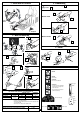
PREPARING THE MACHINE Fitting the handlebar Full of oil - Remove the lock nut (1) and the washer (2). - Fit the handlebar on the shaft from the chassis as shown in the attached drawing, Position the hollowed-out section of the part (3) towards the rear. Full of petrol 1 2 3 - Refit the washer (2) and the nut (1). - Adjust the handlebar’s height and the offset to suit your wishes before locking the nut (1).
1 - ADJUSTING THE HANDLEBAR 3 - CLUTCH a - In height It is essential that you release the clutch reversing system 4 3 before using the 1 Forward 2 Loosen Tighten 3 b - In offset 2 - STARTING 4 Reverse 1 5 4 - STOP 3 2 2 1 3 Stop 4 5 EXPLANATION OF THE PICTOGRAMS Start Stop DANGER 6 DANGER Rotating tools WARNING : Read the user’s manual Fuel control WARNING - Consult the user’s manual and disconnect the spark plug before performing any work on the machine.
Motobinadoras GUIA DEL UTILIZADOR DESCRIPTIVO DE LA MOTOBINADORA 10 16 8 1. Palanca de mando de gases 2. Reja de protección escape 3. Filtro de aire 4. Tapón de depósito de gasolina 5. Lanzador 6. Deflector de escape 7. Tampón de llenado de aceite 8. Mango 9. Mango de embrague 10. Manecilla de marcha adelante/atrás 11. Reglaje de posición del manillar 12. Capó de correa 13. Extensión chapa protectora 14. Espolón de profundidad de arado 15. Herramientas rotativas 16.
CONSIGNAS DE SEGURIDAD Conviene reservar una particular atención a las indicaciones precedidas de las siguientes menciones: ATENCION : Señala un gran riesgo de heridas corporales graves, incluso de peligro mortal de no observarse las instrucciones. PRECAUCION : . Señala una posiblidad de heridas corporales o de deterioro del equipamiento de no observarse las instrucciones. NOTA : Comunica datos de interés.
PREPARACION DE LA MAQUINA Colocación del manillar Llenado de aceite - Quite la tuerca de bloqueo (1) así como la arandela (2). - Coloque el manillar sobre el eje del chasis conforme al esquema siguiente. Llenado de gasolina 1 2 Coloque la parte hueca de la pieza (3) hacia atrás. 3 - Vuelva a colocar la arandela (2) y la tuerca (1) - Ajuste la altura y la posición lateral del manillar según su deseo, antes de bloquear la tuerca (1).
1 - REGLAJE DEL MANILLAR 3 - EMBRAGUE a - En altura ¡ Es imprescindible soltar el embrague inversor 4 3 antes de utilizar el 1 Marcha adelante 2 Aflojar Apretar 3 b - En desvío lateral 2 - PUESTA EN MARCHA Marcha átras 1 4 5 4 - PARADA 3 2 2 1 3 Stop 4 5 EXPLICACION DE LOS PICTOGRAMAS Marcha Stop PELIGRO 6 PELIGRO Herramientas rotativas ¡ ATENCION ! : Leer el manual de utilización ¡ ATENCION ! - Consultar el manual de utilización y desconectar la bujía antes de toda intervención.
Motorhacken BENUTZERHANDBUCH BESCHREIBUNG DER MOTORHACKE 10 16 8 1. 2. 3. 4. 5. 6. 7. 8. 9. 10. 11. 12. 13. 14. 15. 16. 17.
SICHERHEITSBESTIMMUNGEN Die Angaben, die mit folgendem Hinweis gekennzeichnet sind, besonders beachten: ACHTUNG : Hier besteht hohe Verletzungsgefahr, oder sogar Lebensgefahr, falls die Anweisungen nicht berücksichtigt werden. VORSICHT : . Hier besteht Verletzungsgefahr, oder Beschädigungsgefahr der Ausrüstung, falls die Anweisungen nicht berücksichtigt werden. HINWEIS : Erteilt nützliche Ratschläge.
MASCHINE VORBEREITEN Lenker anbringen Öl einfüllen - Blockiermutter (1) und Unterlegscheibe entfernen. - Lenker auf der Achse des Gestells gemäß Zeichnung anbringen. Sichtbaren Teil des Teils (3) hinten ansetzen. - Unterlegscheibe (2) und Mutter (1) anbringen. - Höhe und Radius des Lenkers wunschgemäß einstellen, anschließend mit der Mutter (1) blockieren.
1 - LENKER EINSTELLEN 3 - KUPPLUNG a - Höhe Kupplung 3 lösen, bevor Wendegetriebe 4 benutzt wird. 1 Vorwärtsgang 2 Lösen Anziehen 3 b - Reichweite 2 - INBETRIEBNAHME Rückwärtsgang 1 4 5 4 - ANHALTEN 3 2 2 1 3 Stop 4 5 ERLÄUTERUNG DER PIKTOGRAMME On Stop GEFAHR 6 GEFAHR Rotierende Werkzeuge ACHTUNG : Lesen Sie die Gebrauchsanleitung Gashebel ACHTUNG - Lesen Sie die Gebrauchsanleitung und trennen die Kerze vor jedem Eingriff.
Grondfreesmachine GEBRUIKSHANDLEIDING BESCHRIJVING VAN DE GRONDFREESMACHINE 10 16 8 1. 2. 3. 4. 5. 6. 7. 8. 9. 10. 11. 12. 13. 14. 15. 16. 17.
VEILIGHEIDSVOORSCHRIFTEN Let met name op de aanwijzingen, die voorafgegaan worden door de volgende aanduidingen: WAARSCHUWING : Duidt op een groot risico voor ernstige lichamelijke verwondingen met zelfs eventuele dodelijke afloop als de instructies niet opgevolgd worden. VOORZICHTIG : . Duidt op een risico voor lichamelijke verwondingen of beschadiging van de machine als de instructies niet opgevolgd worden. N.B. : Verstrekking van nuttige informatie.
VOORBEREIDING VAN DE MACHINE Installatie van het stuur Vullen met olie - Verwijder de borgmoer (1) en de ring (2). - Breng het stuur op zijn plaats aan op de as van het chassis volgens de bijgaande afbeelding. Zet het uitgeholde gedeelte van het onderdeel (3) naar achteren toe. Vullen met benzine 1 2 3 - Breng de ring (2) en de moer (1) weer aan. - Stel het stuur in de hoogte en zijwaarts naar wens af, alvorens de moer (1) te blokkeren.
1 - AFSTELLING VAN HET STUUR 3 - KOPPELING a - Hoogteafstelling Men dient verplicht eerst de koppeling rens de omkeerinrichting 4 3 los te laten alvo- te gebruiken.
Motozappa LIBRETTO ISTRUZIONI DESCRIZIONE DELLA MOTOZAPPA 10 16 8 1. 2. 3. 4. 5. 6. 7. 8. 9. 10. 11. 12. 13. 14. 15. 16. 17.
NORME DI SICUREZZA Porre la massima attenzione alle indicazioni precedute dalle diciture seguenti: ATTENZIONE : Segnala rischi elevati di ferite gravi fino al pericolo di morte in caso di mancata osservanza delle istruzioni. AVVERTENZA : . Segnala l’eventuale rischio di ferite o di deterioramento della macchina in caso di mancata osservanza delle istruzioni. NOTA : Fornisce informazioni utili. In caso di problemi e per ogni domanda riguardante la motozappa, rivolgetevi ad un concessionario autorizzato.
PREPARAZIONE DELLA MACCHINA Montaggio della stegola Pieno d’olio - Rimuovere il dado di bloccaggio (1) e la rondella (2). - Posizionare la stegola sull’asse del telaio secondo la figura allegata. Posizionare la parte cava del pezzo (3) verso la parte posteriore. Pieno di benzina 1 2 3 - Rimettere la rondella (2) e il dado (1). - Regolare la stegola in altezza e la sporgenza secondo le vostre esigenze prima di bloccare il dado (1).
1 - REGOLAZIONE DELLA STEGOLA 3 - FRIZIONE a - In altezza È obbligatorio rilasciare la frizione vertitore 4 3 prima di utilizzare l’in- 1 Marcia avanti 2 Allentare Stringere 3 b - In sporgenza 2 - AVVIO Retromarcia 1 4 5 4 - ARRESTO 3 2 2 1 3 Stop 4 5 SIGNIFICATO DEI SIMBOLI Marcia Stop PERICOLO 6 PERICOLO Attrezzi rotanti ATTENZIONE : Leggere il libretto d’istruzioni Comando dei gas ATTENZIONE - Consultar il libretto d’istruzioni e scollegare la candela prima di qualsiasi interve